

A reliable 5-axis CNC setup must hold the workpiece securely while keeping enough clearance for the cutting tool, holder, spindle, fixture, and rotary axes. The part also needs to be positioned and referenced accurately so that features remain aligned when the machine indexes or rotates.
Poor workholding or alignment can cause dimensional errors even when the CAM toolpath is correct. For tight-tolerance parts, setup accuracy depends on fixture rigidity, datum strategy, probing, rotary-axis calibration, tool reach, and minimizing unnecessary reclamping.
Why Is Workholding More Critical in 5-Axis Machining?
In conventional 3-axis machining, the workpiece is usually approached from a relatively limited number of directions. The fixture mainly needs to hold the part rigidly and provide enough access from the top.
5-axis machining is different because the cutting tool can approach the workpiece from multiple orientations.
That added flexibility is one of the main advantages of 5-axis machining, but it also makes workholding more difficult.
A fixture that works well for 3-axis machining may block the tool holder when the spindle tilts toward a side wall. A tall vise may provide excellent clamping force but prevent the machine from accessing angled surfaces or undercuts.
Good 5-axis workholding therefore has to balance two requirements:
Rigidity and accessibility.
The fixture must resist cutting forces without allowing the part to move, but it should also expose as much of the workpiece as possible.
This is especially important for:
- Deep cavities
- Angled holes
- Complex side features
- Undercuts
- Thin-wall aluminum housings
- Parts requiring several machining directions
The strongest fixture is not automatically the best 5-axis fixture. A successful setup must provide enough support without blocking the machining angles that make 5-axis machining useful.
What Makes a Good 5-Axis Workholding Setup?
A good setup usually combines secure clamping, low obstruction, repeatable positioning, and enough clearance for rotary movement.
1. Secure Clamping Without Part Movement
The first requirement is stability.
The workpiece must remain in the same position during roughing, finishing, tool changes, and rotary-axis movement.
Clamping must resist:
- Cutting forces
- Tool engagement changes
- Vibration
- Rotary motion
- Acceleration and deceleration of the machine axes
However, more clamping force is not always better.
Thin-wall aluminum parts can deform under excessive clamping pressure. In some cases, the part measures correctly while still clamped but changes dimension after it is released.
For these components, fixture design should support the part near critical areas while avoiding unnecessary distortion.
2. Maximum Tool Access
One of the main goals of 5-axis machining is to reach multiple surfaces without repeatedly removing and repositioning the part.
A good fixture should expose the features that need to be machined from different angles.
Ideally, one setup allows access to:
- The top surface
- Multiple side faces
- Angled features
- Deep pockets
- Critical holes
- Contoured surfaces
Reducing the number of setups can improve dimensional consistency because fewer datum transfers are required.
Every time a workpiece is removed and reclamped, a new positioning error can be introduced.
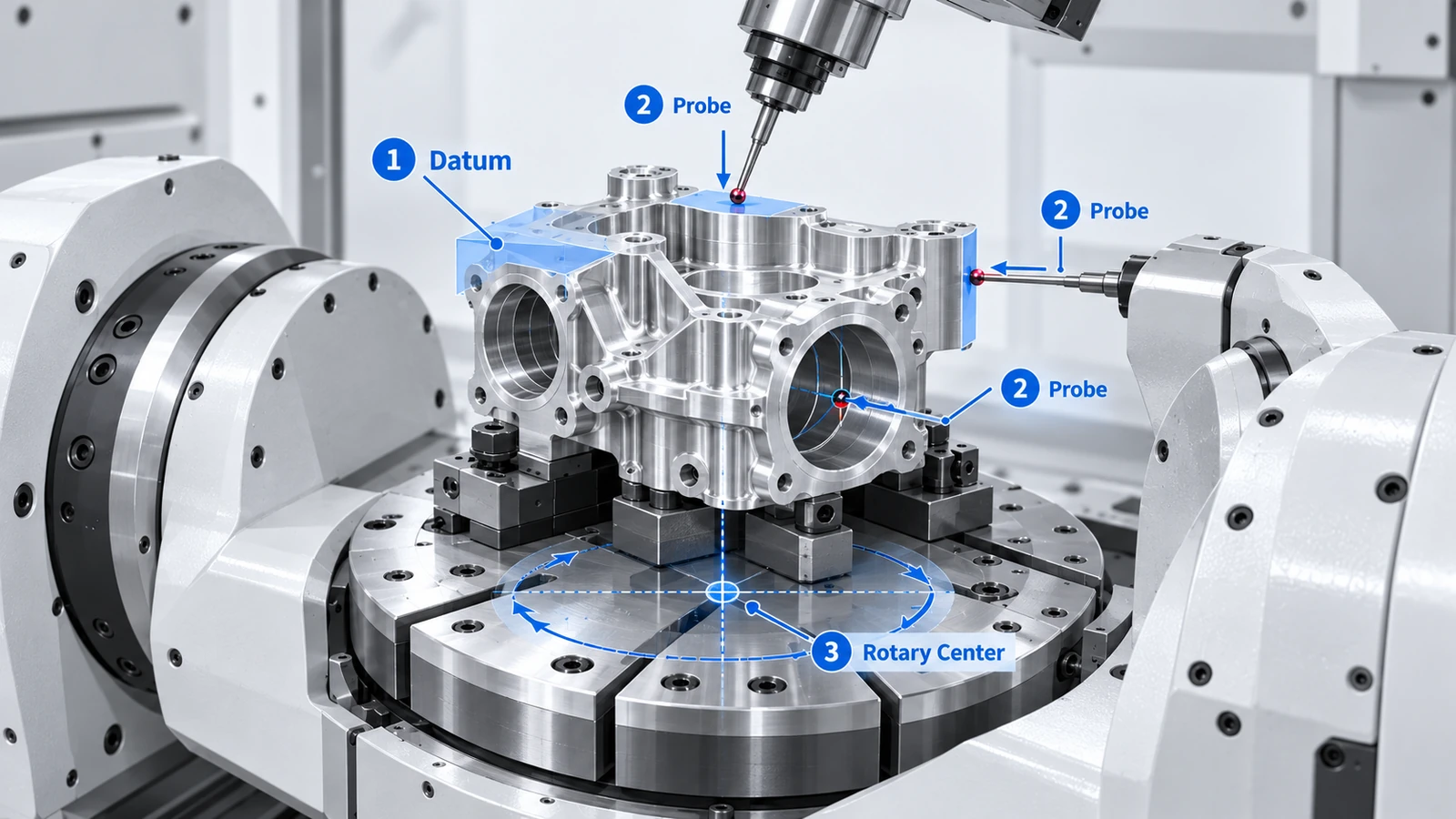
3. Low-Profile Workholding
Fixture height has a major effect on tool access.
A tall vise or clamp may force the programmer to use a longer cutting tool to reach the workpiece.
That can create several secondary problems:
Longer tool reach → lower rigidity → more tool deflection → greater vibration risk → poorer surface finish
Low-profile workholding can reduce these problems by allowing the spindle and holder to approach the workpiece more directly.
For 5-axis machining, the fixture should be designed around the required tool access rather than simply around maximum clamping force.
4. Repeatable Positioning
Repeatability becomes important when machining:
- Multiple identical parts
- Low-volume production batches
- Recurring jobs
- Secondary operations
- Fixtures that need to be removed and reinstalled
Repeatable locating features can reduce setup time and improve consistency between parts.
Zero-point workholding systems are often used for this purpose because they allow a fixture or pallet to return to a known position without manually indicating the entire setup again.
The exact repeatability depends on the specific system, machine condition, installation, and operating environment.
5. Clearance for Rotary Motion
In 5-axis machining, clearance must be checked beyond the cutting edge.
The programmer and setup technician should consider:
- Tool-to-part clearance
- Holder-to-part clearance
- Holder-to-fixture clearance
- Fixture-to-spindle clearance
- Part-to-machine clearance
- Rotary table movement
- Non-cutting approach and retract movements
A setup may look safe when the spindle is vertical but become unsafe after the part or tool rotates.
This is why workholding design should be evaluated together with CAM simulation rather than as a separate decision.
How Is a 5-Axis Part Aligned Accurately?
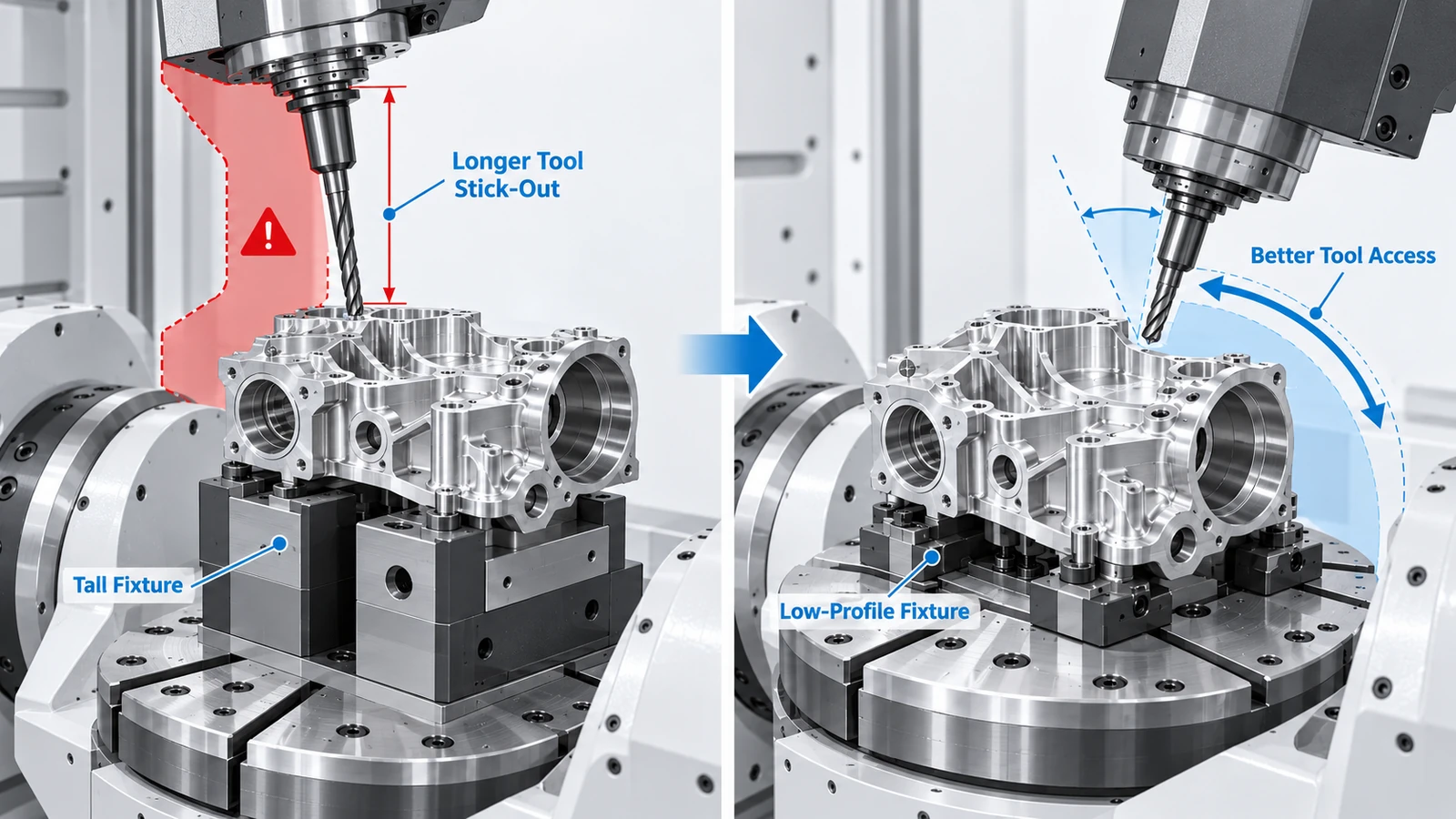
Accurate alignment begins with a clear datum strategy.
The machine must know exactly where the workpiece is located relative to the programmed coordinate system.
Step 1: Establish a Reliable Datum
The datum should be stable, repeatable, and related to important part features whenever possible.
Common references include:
- Machined datum surfaces
- Precision bores
- Locating pins
- Fixture reference surfaces
- Zero-point fixture locations
The goal is to create a reliable relationship between the physical part and the CAM coordinate system.
A weak or inconsistent datum can create positioning errors even when the machine itself is accurate.
Step 2: Probe the Workpiece
Touch probes can be used to confirm the actual workpiece position before machining.
Depending on the setup, probing may verify:
- X position
- Y position
- Z height
- Bore center
- Surface orientation
- Part rotation
- Fixture location
Probing is especially useful when the workpiece must be positioned precisely before machining features from several orientations.
It can also reveal whether the part is not seated correctly or has shifted from the intended location.
Step 3: Confirm the Work Offset
The probed location must be correctly transferred into the machine’s work coordinate system.
An incorrect work offset can shift the entire machining program even if the toolpath itself is correct.
For complex parts, this may result in features appearing correctly shaped but positioned incorrectly relative to other datums.
Step 4: Verify the Rotary Center
This is one of the most important differences between 3-axis and 5-axis setup.
In 5-axis machining, the workpiece or cutting tool rotates around one or more rotary centers.
The control system must understand the relationship between:
- Linear machine axes
- Rotary-axis centers
- Workpiece position
- Tool position
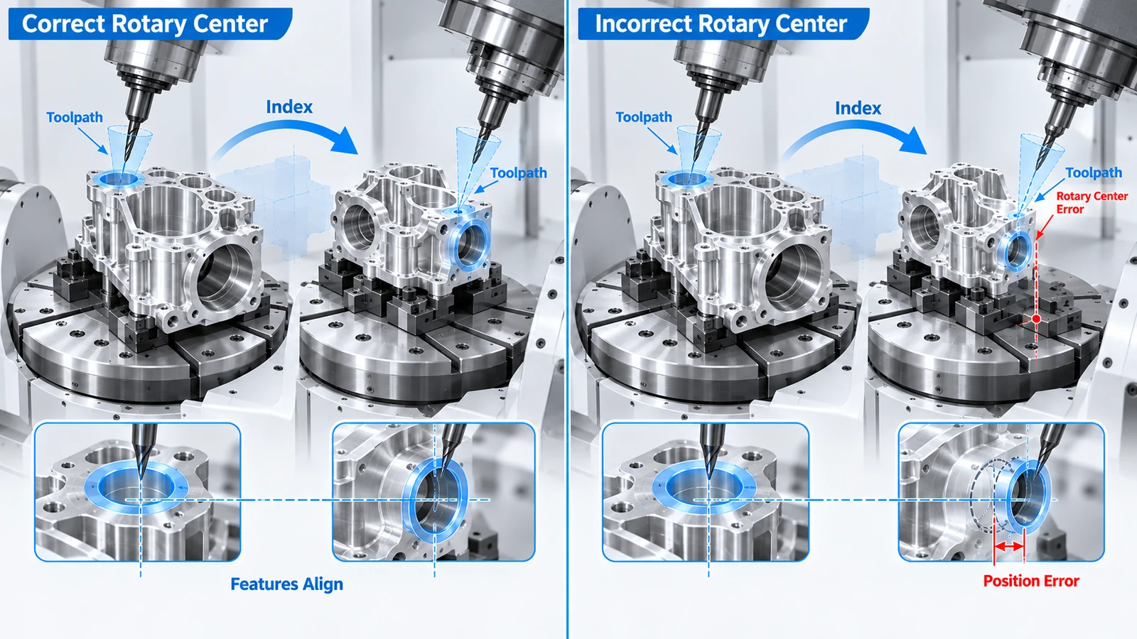
If the actual rotary center does not match the machine’s calibrated kinematic parameters, positional errors can appear when the machine indexes to a different angle.
A feature may be correct at one orientation but shift when the rotary axes move.
For this reason, rotary-axis calibration is a critical part of maintaining 5-axis accuracy.
How Does Setup Error Affect 5-Axis Accuracy?
A precise machine does not automatically guarantee a precise part.
Part accuracy is the result of the entire machining system.
That system includes:
Machine accuracy + fixture stability + datum accuracy + probing accuracy + tool condition + thermal stability + rotary-axis calibration
If one part of the system is incorrect, the final component can still be out of tolerance.
Some common setup-related problems include:
| Setup problem | Possible result |
|---|---|
| Part is not seated flat | Angular or dimensional error |
| Fixture moves under cutting load | Position shift or chatter |
| Incorrect work offset | Entire feature location shifts |
| Probe is not calibrated correctly | Incorrect datum position |
| Rotary center is inaccurate | Features move after indexing |
| Tool stick-out is excessive | Deflection and poor surface finish |
| Thin-wall part is overclamped | Dimension changes after unclamping |
This is why troubleshooting a 5-axis accuracy problem should not begin with the assumption that the CAM program is wrong.
The setup itself may be the source of the error.
Common 5-Axis Setup Problems and How to Fix Them
Many setup problems become visible only when the toolpath and fixture are evaluated together.
| Problem | Likely cause | Better approach |
|---|---|---|
| Holder cannot reach a side wall | Fixture is too high | Use lower-profile workholding or change orientation |
| Part moves during roughing | Insufficient support or clamping | Improve support and revise clamp location |
| Features do not align after indexing | Datum or rotary calibration error | Verify probing, offsets, and rotary center |
| Surface finish becomes worse at an angle | Excessive tool reach or reduced rigidity | Use a shorter tool and better tool orientation |
| Thin wall changes size after unclamping | Excessive clamping force | Reduce distortion and support the part more evenly |
| Setup takes too long to repeat | Fixture must be manually re-indicated | Use repeatable locating or zero-point workholding |
| Spindle cannot approach the part safely | Fixture blocks rotary motion | Redesign the fixture or change setup orientation |
One of the most common mistakes is solving every access problem by using a longer tool.
A longer tool may clear the fixture, but it can also increase deflection and reduce cutting stability.
In many cases, changing the fixture height, tool orientation, or machining sequence produces a better result.
Example: Setting Up a Deep-Cavity Aluminum Housing
Consider a precision aluminum housing with a deep internal cavity, several side holes, and angled features.
The main challenge is not simply cutting the cavity.
The part must remain stable while allowing the machine to reach several sides without excessive reclamping.
The Setup Challenge
A traditional vise may hold the part securely but block access to side features.
Using a taller fixture may also force the programmer to use long tools when machining deep internal walls.
If the part is removed and reclamped several times, critical features may accumulate positioning errors between setups.
A Better Setup Strategy
A lower-profile fixture can expose more of the workpiece while maintaining sufficient support.
The setup can then be probed to establish the main datum and confirm the physical part position.
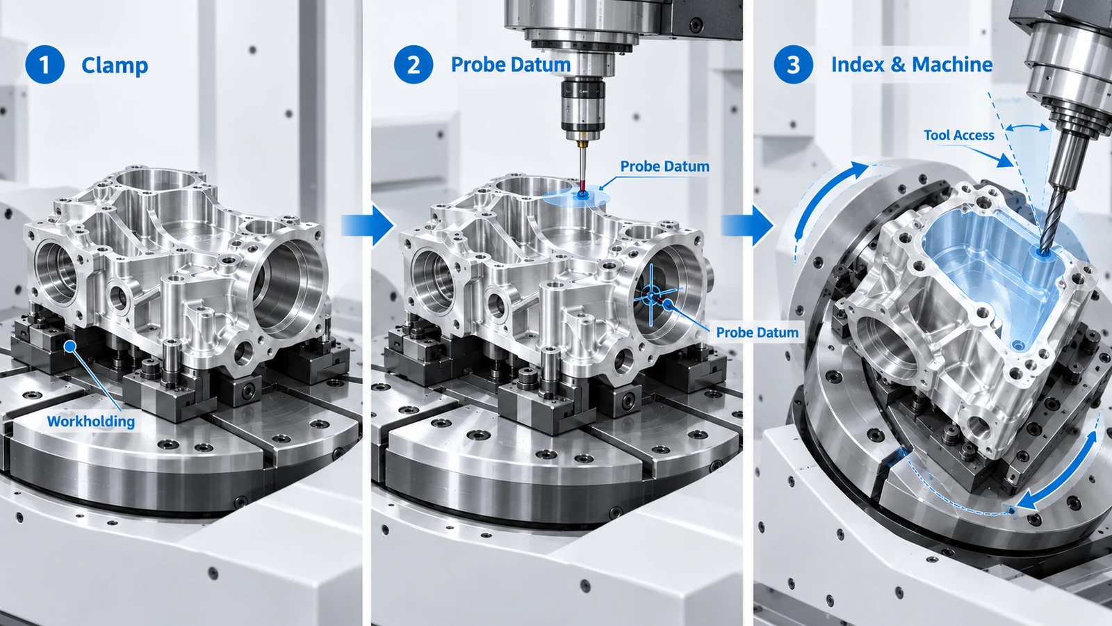
A typical process may include:
- Load and locate the workpiece.
- Probe the primary datum.
- Confirm work offsets.
- Rough the deep cavity.
- Index the rotary axes to reach side features.
- Finish critical surfaces with shorter tools where possible.
- Verify key dimensions before removing the part.
The objective is to reduce unnecessary datum transfers while maintaining tool and holder clearance.
For complex housings, this can improve both efficiency and positional consistency.
3+2 or Simultaneous 5-Axis: Which Is Better for Accuracy?
Simultaneous 5-axis machining is not automatically more accurate than 3+2 machining.
The correct choice depends on the geometry.
In 3+2 machining, the rotary axes position the workpiece or tool at a fixed angle and then remain stationary while cutting occurs.
This can provide a stable machining condition for:
- Angled holes
- Planar surfaces
- Indexed side features
- Features that do not require continuous tool orientation changes
Simultaneous 5-axis machining is more useful when the tool orientation must change continuously while cutting.
Typical examples include:
- Complex freeform surfaces
- Impellers
- Blades
- Deep curved surfaces
- Features requiring continuous collision avoidance
For many prismatic parts, 3+2 machining can be the better choice because the cutting motion is simpler and rotary-axis movement is reduced.
The goal should not be to use simultaneous 5-axis motion whenever possible.
The goal is to use the simplest machining strategy that maintains access, accuracy, surface quality, and efficiency.
Reliable 5-Axis Accuracy Starts With the Setup
Accurate 5-axis machining starts before the cutting tool touches the workpiece.
The fixture must hold the part rigidly without blocking tool access. The datum must be repeatable. Work offsets and probing need to be correct, and the machine’s rotary-axis relationship must be properly calibrated.
For complex components with deep cavities, angled features, or tight positional relationships, reducing unnecessary setups can help improve machining consistency.
Frequently Asked Questions
Workholding directly affects rigidity, tool access, repeatability, and part accuracy. A poor fixture can block machining angles, create vibration, introduce positioning errors, or cause collisions even when the CAM program is correct.
Not always. The fixture depends on part geometry, production quantity, required accuracy, and tool access. Standard vises may work for simple parts, while complex components may require low-profile, custom, modular, or zero-point workholding.
Possible causes include incorrect work offsets, probing errors, rotary-axis calibration errors, fixture movement, machine geometry, or thermal effects. The source should be identified systematically rather than assuming the toolpath is incorrect.
Not necessarily, but 3+2 machining can provide a more stable cutting condition when continuous rotary motion is unnecessary. For many indexed features, it offers simpler machine movement while still providing multi-side access.



