

A blind hole is a hole that does not go all the way through a part. It starts at the surface and extends to a specified depth, leaving the bottom closed. Unlike a through hole, a blind hole has only one open end.
Blind holes are common in machined components, especially when a part needs to maintain a seal, prevent breakthrough, or keep the opposite surface free of openings.

Blind Hole vs. Through Hole: What's the Difference?
The main difference is simple: a through hole goes completely through a part, while a blind hole stops at a specified depth.
This difference affects several aspects of machining:
- Chip evacuation: Through holes generally allow chips to exit more easily. In blind holes, chips must be removed through the opening, increasing the risk of chip buildup and drill breakage.
- Depth control: Through holes only need to break through the material. Blind holes require accurate depth control. Drilling too deep can break through the remaining wall, while drilling too shallow can leave insufficient thread engagement.
- Inspection: Through holes are generally easier to inspect with conventional gauges. Blind holes may also require depth measurements and verification of the bottom geometry.
As a general design guideline, use a through hole when possible unless there is a specific reason to keep the bottom closed. Common reasons include sealing requirements, appearance constraints, and applications where the hole bottom must support another component.
What Are the Different Types of Blind Holes?
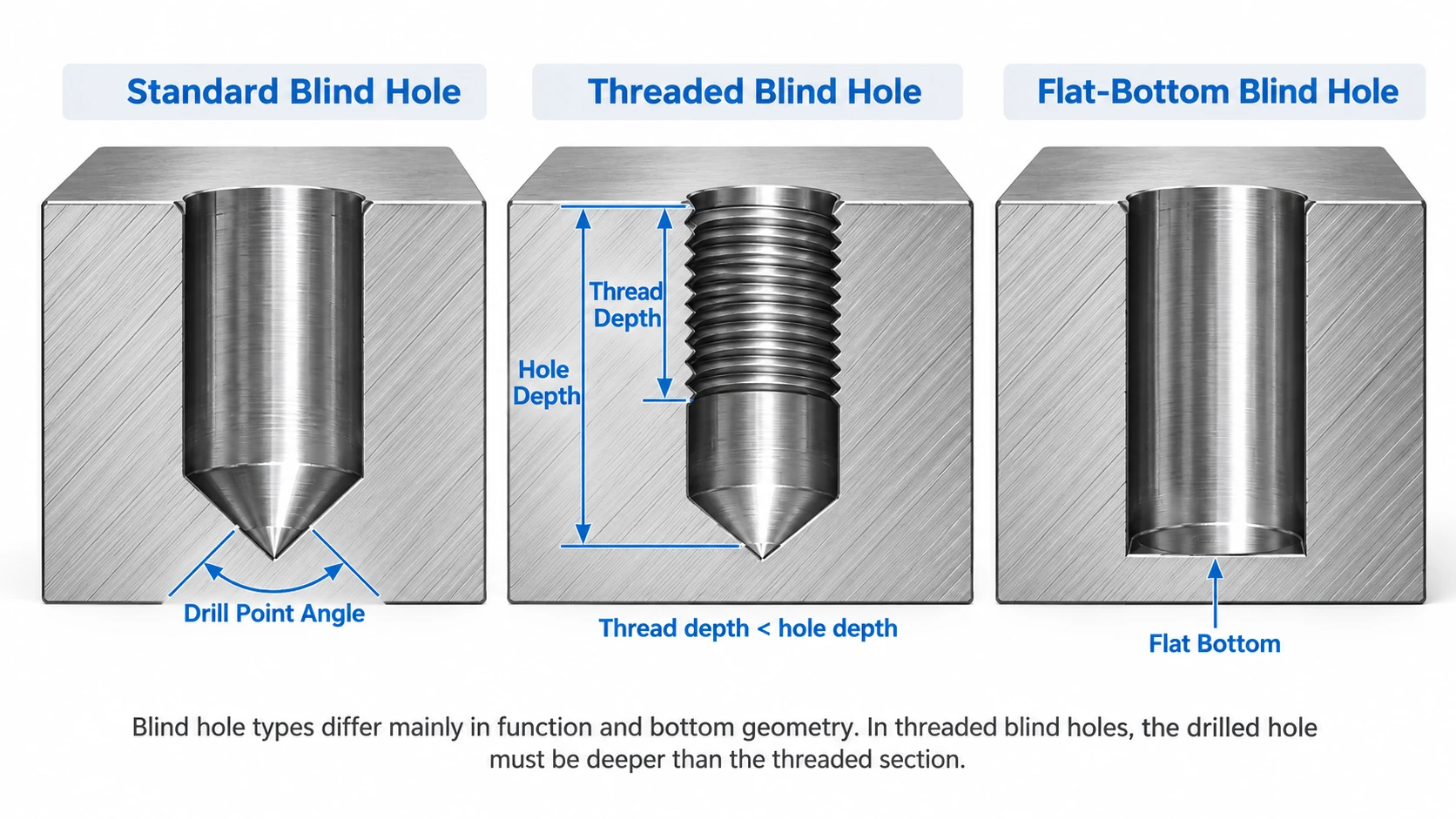
Blind holes can be divided into three common types based on their purpose and bottom geometry.
Standard Blind Holes
A standard blind hole is produced using a conventional drill bit, leaving a conical bottom that matches the drill point angle.
This is the most common and cost-effective option for general mounting and locating features.
Threaded Blind Holes
A threaded blind hole has internal threads for fastening bolts or screws.
The key requirement is sufficient usable thread depth. Additional clearance must be provided at the bottom for the tap’s lead threads and chip accumulation. Without enough clearance, the tap may bottom out, resulting in incomplete threads or tool breakage.
Flat-Bottom Blind Holes
A flat-bottom blind hole has a flat surface at the bottom instead of a conical drill point.
Conventional drill bits cannot produce a fully flat bottom. A flat-bottom drill or end mill is typically required.
These holes are useful when a pin, spacer, or other component must seat against the bottom surface.
How Are Blind Holes Dimensioned on Engineering Drawings?
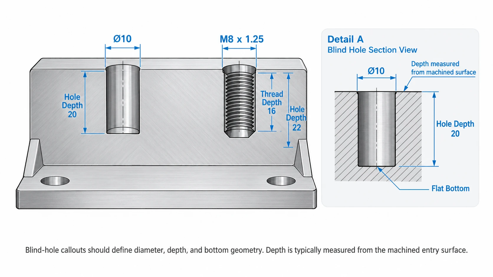
A blind hole drawing should clearly specify three things: diameter, depth, and bottom geometry.
Hole Diameter
Hole diameter is typically indicated by the diameter symbol (Ø) followed by the required dimension.
Hole Depth
Depth is commonly indicated using a depth symbol or a written depth callout.
The drawing should clearly identify the surface from which the depth is measured. In most cases, this is the surface where the hole begins. For parts with multiple surfaces, the reference surface should be clearly defined.
Bottom Geometry
The bottom shape is easy to overlook.
A standard drilled blind hole typically has a conical bottom corresponding to the drill point angle, commonly 118° or 135°.
If a flat bottom is required, the drawing should explicitly call it out or show the required geometry. Otherwise, the machinist may use a conventional drill, leaving a conical bottom that prevents a pin or other component from seating properly.
Threaded Blind Hole Dimensions
For threaded blind holes, the drawing should specify the thread size, required thread depth, and drilled hole depth.
Thread depth and drilled hole depth are not the same. The drilled hole usually needs to be deeper than the required full-thread depth to provide clearance for the tapping tool.
How to Drill a Blind Hole
Drilling a blind hole on a CNC machine is relatively straightforward, but several details are important for maintaining accuracy and preventing tool damage.
Step 1: Set the Drilling Depth
Program the required drilling depth and verify the tool position and depth offsets.
For production runs, measure the first completed hole to confirm that the depth meets the drawing requirements before continuing.
Step 2: Manage Chip Evacuation
Chip evacuation is one of the biggest challenges in blind hole drilling.
As the drill moves deeper, chips must travel back through the hole opening. Poor chip evacuation can cause chip packing, excessive cutting forces, and drill breakage.
Common solutions include:
- Peck drilling: The drill periodically retracts to help break and remove chips.
- Through-tool coolant: Coolant flows through internal channels in the drill to help flush chips out of the hole.
Aluminum can also cause problems because some alloys tend to form built-up edges and stick to cutting tools when chip evacuation or lubrication is inadequate.
Step 3: Control the Bottom Geometry
A conventional drill leaves a conical bottom.
If the drawing requires a flat bottom, a flat-bottom drill or end mill may be needed to finish the hole.
Flat-bottom machining requires careful control of feed rates and tool engagement. Excessive cutting forces can affect bottom flatness or cause tool deflection.
Common Blind Hole Drilling Problems
| Problem | Possible Solution |
|---|---|
| Hole location error or drill wandering | Use a spot drill or suitable hole-starting method |
| Incorrect hole depth | Verify tool offsets and inspect the first part |
| Chip buildup or drill breakage | Improve chip evacuation using suitable peck cycles or through-tool coolant |
| Uneven hole bottom | Use an appropriate flat-bottom cutting tool and adjust cutting parameters |
Blind Hole Design Guidelines
There are four main factors to consider when designing blind holes.
1. Depth-to-Diameter Ratio
The depth-to-diameter ratio is calculated by dividing the hole depth by its diameter.
For conventional drilling, a depth-to-diameter ratio of approximately 3:1 to 4:1 is often a practical starting point.
Beyond approximately 5:1, chip evacuation and drill deflection can become more challenging, depending on the drill, material, and machining conditions.
Deeper holes may require specialized drills, multiple drilling operations, or deep-hole drilling techniques, which can increase machining costs.
2. Bottom Geometry
A conical drill-point bottom is generally less expensive to produce, but it occupies additional space at the bottom of the hole.
A flat bottom provides a seating surface but usually requires additional machining.
Consider whether another component needs to contact the bottom of the hole. If it does, a flat-bottom design may be appropriate. For general mounting or weight-reduction features, a standard drilled bottom may be sufficient.
3. Remaining Wall Thickness
Blind holes must leave enough material between the hole bottom and the opposite surface of the part.
If the remaining wall is too thin, drilling may break through the material, or the part may crack or deform under operating loads.
A remaining wall thickness of approximately 0.5 to 1 times the hole diameter can serve as an initial design reference, but the actual requirement depends on material strength, part geometry, and loading conditions.
4. Depth Tolerance
Blind hole depth does not always need an extremely tight tolerance, but it must be controlled well enough for the intended application.
For threaded blind holes, the drilled depth must provide sufficient usable threads while leaving clearance for the tapping operation.
For locating holes, the depth must allow the pin or mating component to seat correctly.
Unnecessarily tight tolerances increase manufacturing costs, while overly loose tolerances can lead to assembly problems.
Where Are Blind Holes Used?
Blind holes are commonly used in three types of applications.
Sealed Components
Blind holes are used in hydraulic systems, pneumatic components, and engine oil or coolant passages where drilling completely through the material could create an unwanted leak path.
Parts That Cannot Be Drilled Through
Some components require an uninterrupted outer surface for appearance, structural integrity, or assembly clearance.
Blind holes allow mounting features to be added without breaking through the opposite side.
Locating and Fastening Features
Blind holes are commonly used for dowel pins, threaded mounting holes, and set screws.
These features only need a specified depth to provide positioning or fastening, rather than extending completely through the part.
When Should You Avoid Blind Holes?
Blind holes may not be the best choice for very deep holes with difficult chip evacuation, passages that must allow fluid to flow through, or applications where deep drilling would significantly increase costs.
A useful question during design is: Does this hole actually need to stop inside the part?
If the answer is no, a through hole may be a simpler and more economical option.
Frequently Asked Questions
Not completely with a conventional tap. The lead threads at the front of the tap cannot produce full threads all the way to the bottom. The drilled hole must provide additional clearance beyond the required usable thread depth.
Use a flat bottom when a pin or another component needs to seat firmly against the bottom surface. For standard mounting or weight-reduction features, a conventional conical drill-point bottom is usually sufficient and less expensive.
Blind hole depth can be measured using depth gauges, depth micrometers, or specialized depth inspection tools. A coordinate measuring machine (CMM) may be used for certain precision inspection requirements, depending on the hole geometry and accessibility. The first part should be inspected before production continues, followed by appropriate in-process or sampling inspections.
It depends on the hole depth, geometry, and tolerance requirements. A shallow blind hole may cost about the same as a through hole. However, deep blind holes, flat-bottom requirements, and difficult chip evacuation can increase machining time, tool wear, and the risk of tool breakage, resulting in higher costs.


