

In 5-axis machining, the best toolholder is not simply the shortest, longest, or most rigid option. It must provide enough clearance to reach the feature while keeping the tool assembly as short and rigid as practical.
For deep cavities, steep walls, undercuts, and complex multi-angle features, engineers must evaluate the complete spindle–holder–tool assembly. Tool reach, holder diameter, gauge length, stick-out, rigidity, and tool orientation all affect whether a feature can be machined safely and accurately.
Why Does Toolholder Selection Matter More in 5-Axis Machining?
In 3-axis machining, the cutting tool usually approaches the workpiece from a relatively fixed direction. Toolholder clearance is important, but the available access is easier to predict.
5-axis machining changes the geometry of the problem.
As the tool tilts or the workpiece rotates, the complete tool assembly moves through a much larger spatial envelope. The cutting edge may have enough room to reach the surface while the holder body, spindle nose, or tool shank approaches another part of the workpiece.
This means the real question is not only:
Can the cutting tool reach the feature?
It is:
Can the complete spindle–holder–tool assembly reach the feature with enough clearance and enough rigidity to machine it accurately?
This becomes especially important for:
- Deep pockets
- Steep cavity walls
- Undercuts
- Narrow openings
- Complex side features
- Freeform surfaces
- Parts requiring large tool tilt angles
In many 5-axis operations, the toolholder becomes the limiting geometry before the cutting edge does.
The Main Trade-Off: Reach vs. Rigidity
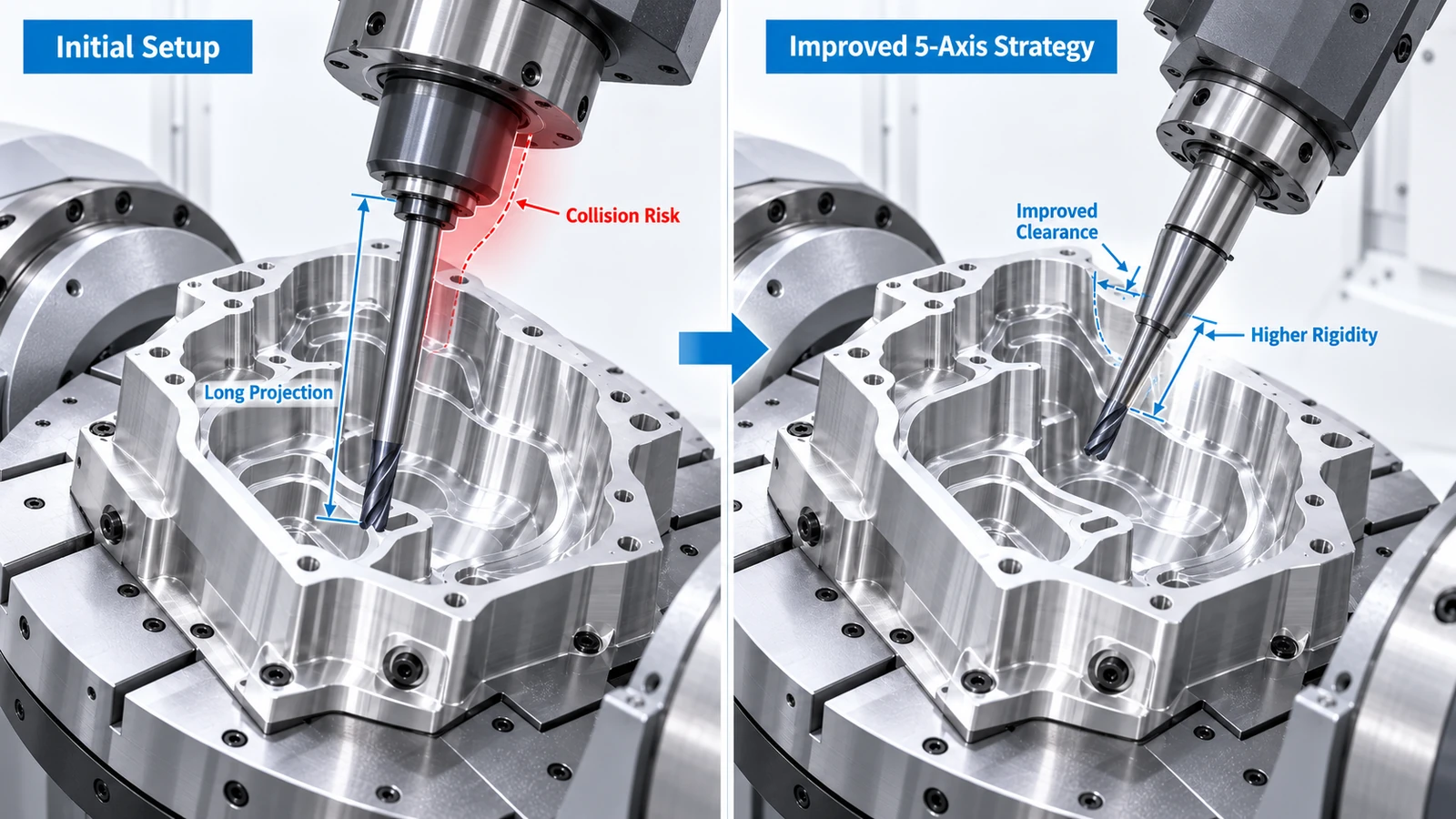
The most important toolholding decision in 5-axis machining is often the balance between reach and rigidity.
A longer tool assembly improves access.
But additional length also reduces stiffness.
The basic relationship is straightforward:
More reach → longer tool assembly → lower rigidity → more deflection and vibration risk
A longer tool may allow the cutter to reach the bottom of a deep cavity, but it can also create:
- Chatter
- Tool deflection
- Tapered walls
- Poor surface finish
- Dimensional error
- Shorter tool life
For this reason, one of the most useful 5-axis principles is:
Use the shortest practical tool assembly that can safely reach the feature.
This is where 5-axis positioning becomes valuable.
Instead of extending the cutter farther from the holder, the machine can often tilt the tool or rotate the part to create a better approach angle.
That can improve access while keeping the tool shorter and more rigid.
Tool Stick-Out vs. Holder Gauge Length
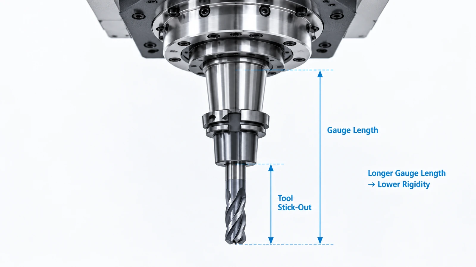
Tool stick-out and gauge length are related, but they are not the same thing.
Tool Stick-Out
Tool stick-out is the distance the cutting tool extends beyond the holder.
Excessive stick-out reduces tool rigidity and increases deflection.
When machining deep cavities, programmers often increase stick-out to avoid holder interference. This can solve a clearance problem but create a cutting stability problem.
Gauge Length
Gauge length describes the overall distance from the spindle reference plane to the working end of the tool assembly.
It is affected by:
- Toolholder length
- Collet or chuck geometry
- Cutter length
- Tool projection
A long gauge length increases the physical envelope of the tool assembly.
This can affect both rigidity and machine clearance.
In 5-axis machining, engineers should therefore evaluate the complete assembly rather than looking only at cutter length.
A short cutter installed in a very long holder may still produce unnecessary overhang.
Likewise, a compact holder with controlled tool projection may provide better stiffness and clearance.
Which Toolholder Type Is Best for 5-Axis Machining?
There is no single best holder for every 5-axis part.
The correct choice depends on:
- Feature geometry
- Cutter diameter
- Required reach
- Material
- Cutting forces
- Spindle interface
- Surface finish requirements
- Clearance around the workpiece
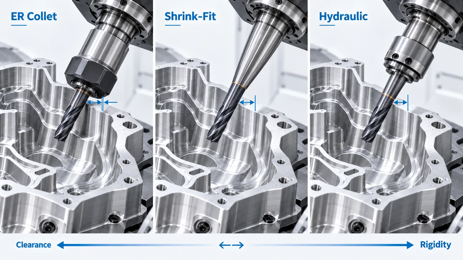
Different holder types offer different trade-offs.
| Toolholder type | Clearance | Rigidity | Typical use |
|---|---|---|---|
| ER collet holder | Moderate | Good | General milling and flexible tool changes |
| Shrink-fit holder | Excellent | High | Complex access, finishing, deep cavities |
| Hydraulic holder | Good | High | Precision finishing and low runout applications |
| Side-lock holder | Limited profile efficiency | High | Heavy cutting and roughing |
ER Collet Holders
ER collet holders are versatile and widely used.
They offer:
- Flexible tool diameter range
- Convenient tool changes
- Good general-purpose rigidity
However, their external nut geometry can increase holder diameter near the cutter.
In tight cavities, this may limit access.
Shrink-Fit Holders
Shrink-fit holders are particularly useful in 5-axis applications because they can combine:
- Compact external geometry
- Good rigidity
- Low runout
- Good access around steep walls
A slim nose profile can help the cutter approach deep or complex surfaces without requiring excessive tool projection.
Hydraulic Holders
Hydraulic holders provide good damping and low runout.
They can be useful for precision finishing where:
- Surface quality is important
- Tool runout must be controlled
- Stable cutting is required
Their suitability still depends on the available external clearance.
Side-Lock Holders
Side-lock holders provide strong mechanical grip and are commonly used for heavy cutting.
However, their geometry may not be ideal for tight 5-axis access.
They are more suitable when rigidity and cutting load are more important than slim toolholder geometry.
How Much Clearance Does a 5-Axis Toolholder Need?
There is no universal clearance value for every job.
Clearance depends on:
- Holder geometry
- Tool orientation
- Workpiece geometry
- Fixture location
- Machine kinematics
- Rotary-axis position
Several interference relationships should be checked.
Holder-to-Part Clearance
The holder must clear cavity walls, ribs, bosses, and nearby geometry throughout the toolpath.
Holder-to-Fixture Clearance
A cutter may clear the workpiece but collide with a clamp or fixture component after the tool tilts.
Spindle-to-Part Clearance
At large tilt angles, the spindle nose can approach the workpiece even when the holder itself remains clear.
Spindle-to-Fixture Clearance
Tall fixtures can restrict usable tool orientations.
This is one reason low-profile workholding is valuable in 5-axis machining.
Machine-to-Machine Clearance
On trunnion-style or rotary-table machines, the fixture, table, workpiece, spindle, and machine structure must remain clear during indexing and simultaneous movement.
These risks should be evaluated before the program reaches the machine.
Why Is a Longer Tool Often the Wrong Solution?
When a holder collides with a cavity wall, the most obvious solution is often:
Use a longer tool.
Sometimes this is necessary.
But it should not automatically be the first choice.
Consider a deep aluminum cavity.
A standard holder approaches the wall during finishing.
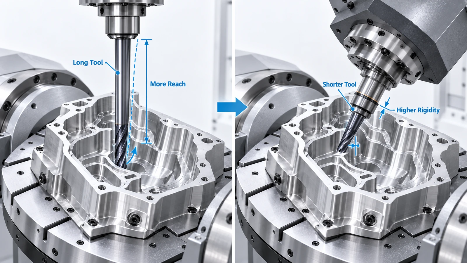
One solution is to extend the cutter farther from the holder.
This provides more reach, but it also increases:
- Deflection
- Chatter risk
- Tool load sensitivity
- Surface finish variation
A better solution may be:
- Tilt the tool
- Rotate the workpiece
- Use a slimmer holder
- Reduce fixture height
- Change the machining direction
- Select a different cutter geometry
The advantage of 5-axis machining is that access can often be improved geometrically rather than simply by increasing tool length.
Choosing Cutting Tools for 5-Axis Geometry
Toolholder selection is only one part of the tool assembly.
The cutting tool geometry should also match the feature being machined.
Flat End Mills
Best suited to:
- Planar surfaces
- Pocket floors
- Side walls
- General roughing
When orientation allows, a larger flat end mill can improve rigidity and material removal rate.
Ball Nose End Mills
Commonly used for:
- Freeform surfaces
- Curved contours
- Mold surfaces
- Complex finishing
5-axis tool tilt can move the contact point away from the center of the ball nose cutter, improving cutting action.
Bull Nose End Mills
Useful for:
- Semi-finishing
- Large contoured surfaces
- Floor-to-wall transitions
- Applications requiring stronger cutter edges
Lollipop and Undercut Cutters
Useful for:
- Undercuts
- Back-side features
- Hidden radii
- Internal recesses
These tools can provide access that conventional end mills cannot, but their neck geometry may limit rigidity.
The goal is not to use one tool for the entire part.
The goal is to use the most stable tool for each feature.
How Tool Tilt Changes Cutting Performance
Tool tilt is not only useful for collision avoidance.
It can also improve cutting performance.
Ball nose cutters provide a good example.
When the cutter center contacts the surface, the local cutting speed near the center is very low.
This can cause:
- Rubbing
- Poor chip formation
- Inconsistent surface finish
- Localized tool wear
By tilting the tool, the contact point moves away from the cutter center.
This can improve:
- Effective cutting speed
- Surface finish
- Tool life
- Cutting stability
However, tool tilt also changes the position of the holder and spindle.
An angle that improves cutting performance may reduce clearance.
Tool orientation must therefore be selected by considering both:
Cutting conditions and collision clearance.
Why Runout Matters More With Small 5-Axis Tools
Runout is the difference between the tool’s intended rotational center and its actual cutting path.
Small amounts of runout can become more important when using:
- Small-diameter end mills
- Finishing tools
- Long-reach tools
- High spindle speeds
Excessive runout can cause one cutting edge to remove more material than the others.
Possible results include:
- Uneven tool wear
- Poor surface finish
- Dimensional variation
- Premature tool failure
This is one reason precision holders such as shrink-fit and hydraulic systems are often considered for demanding 5-axis finishing operations.
But holder type alone does not guarantee good runout.
Tool cleanliness, spindle condition, holder quality, assembly, and tool condition all matter.
Toolholder Clearance vs. Rigidity: Which Should You Prioritize?
Neither should be optimized independently.
A rigid holder that cannot reach the feature is unusable.
A very slim holder that allows access but lacks sufficient stability can also produce poor results.
A better selection process balances:
- Reach
- Holder diameter
- Gauge length
- Tool stick-out
- Rigidity
- Runout
- Cutting load
- Surface finish
- Collision clearance
For example:
| Option | Main advantage | Main limitation |
|---|---|---|
| Large rigid holder | High stiffness | Limited cavity clearance |
| Slim holder | Better access | May reduce rigidity |
| Long tool | Increased reach | Higher deflection risk |
| Short tool with tilt | Better rigidity | Requires suitable machine orientation |
| Shrink-fit assembly | Compact and rigid | Requires dedicated tooling system |
The best solution is usually the one that provides enough clearance with the shortest practical assembly.
Common Tool and Toolholder Problems in 5-Axis Machining
| Problem | Likely cause | Better approach |
|---|---|---|
| Holder contacts cavity wall | Holder body too large | Use a slimmer holder or change tool angle |
| Cutter vibrates in deep cavity | Excessive stick-out | Shorten tool or improve access orientation |
| Finish changes across surface | Tool deflection or poor contact point | Improve rigidity or adjust tool tilt |
| Small cutter breaks frequently | Excessive cutting load | Reduce engagement or revise toolpath |
| Undercut cannot be reached | Cutter geometry is unsuitable | Use dedicated undercut tooling |
| Tool clears part but lacks stability | Tool assembly too long | Reduce gauge length or reposition the part |
| Holder clears workpiece but hits fixture | Fixture blocks approach angle | Change fixture or machining direction |
These problems show why cutter, holder, fixture, and toolpath should be evaluated together.
Example: Tool Selection for a Deep-Cavity Aluminum Housing
Consider a complex aluminum housing with a deep cavity, narrow side walls, and angled internal features.
A standard holder and long end mill can physically reach the bottom of the cavity.
However, this setup creates two problems:
- The tool projection is long.
- The holder approaches the cavity wall during angled finishing.
Option A: Use a Longer Tool
Increasing cutter stick-out improves holder clearance.
But the longer tool becomes less rigid.
Possible consequences include:
- Deflection
- Chatter
- Wall taper
- Poorer surface finish
Option B: Improve Tool Orientation
A better strategy is to tilt the tool or rotate the workpiece so the cutter approaches the wall more directly.
This may allow:
- Shorter cutter projection
- Smaller holder envelope
- Better rigidity
- Improved cutting stability
If additional clearance is still required, a slim shrink-fit holder may provide enough access without extending the cutter as far.
This approach uses 5-axis motion to solve the access problem rather than relying only on longer tooling.
How CAM Simulation Helps Select Toolholders
Toolholder selection should be verified in CAM before machining.
The simulation should include the complete tool assembly whenever possible.
Engineers should check:
- Tool-to-part clearance
- Holder-to-part clearance
- Holder-to-fixture clearance
- Spindle clearance
- Rotary-axis motion
- Approach and retract movements
If interference is detected, several variables can be adjusted:
- Tool tilt
- Holder geometry
- Tool stick-out
- Gauge length
- Machining direction
- Fixture orientation
This process is closely related to collision verification in 5-axis programming.
A tool assembly should not be considered suitable until it has been evaluated in the actual machining orientation.
A Practical Tool Selection Process
A useful 5-axis tooling workflow can follow six steps.
1. Analyze the Feature
Identify:
- Depth
- Width
- Corner radius
- Undercuts
- Surface curvature
- Required access angle
2. Choose the Largest Practical Cutter
A larger cutter generally provides better rigidity and higher productivity.
Use smaller cutters only where the geometry requires them.
3. Minimize Tool Stick-Out
Use only the projection required to reach the feature.
4. Select the Holder Profile
Choose a holder that clears the surrounding geometry without sacrificing unnecessary rigidity.
5. Optimize Tool Orientation
Use 5-axis positioning to improve tool access and reduce assembly length.
6. Simulate the Complete Setup
Check the tool, holder, fixture, spindle, and machine movement before releasing the program.
Better 5-Axis Tooling Starts With the Complete Assembly
5-axis tooling decisions should not be based on cutter type alone.
The complete spindle–holder–tool assembly must provide enough reach, sufficient rigidity, acceptable runout, and safe clearance around the workpiece and fixture.
For many complex parts, the best solution is not a longer cutter but a better combination of tool orientation, holder geometry, fixture design, and toolpath strategy.
Frequently Asked Questions
There is no universal best option. Shrink-fit holders are often useful for complex access because of their compact geometry and rigidity, while ER, hydraulic, or side-lock holders may be better for other operations.
Shorter tools are generally more rigid and less sensitive to deflection and vibration. 5-axis positioning can often provide access from a better angle, allowing shorter tooling to be used.
Only when necessary. A longer tool improves reach but reduces rigidity. Changing the tool angle, holder type, fixture, or machining direction may provide better clearance with less overhang.
Yes. Holder geometry affects the tool length and rigidity required to access the feature. Excessive assembly length or runout can contribute to vibration and surface finish problems.



