
What Is a 5 Axis CNC Machine? 2026 Latest Guide

A 5-axis CNC machine is a CNC machine capable of moving a cutting tool or workpiece along five different axes at the same time. Compared with traditional 3-axis machining, it can produce complex parts with fewer setups, higher precision, and better surface finishes.

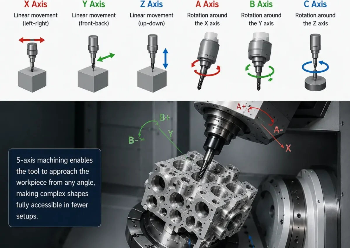
The machine combines three linear axes (X, Y, and Z) with two rotational axes (A, B, or C), allowing the tool to approach the part from multiple directions during machining.

In CNC machining, what does “5-axis” mean?

In the context of CNC milling, “5-axis” refers to a machine tool’s ability to simultaneously control the movement of the tool or workpiece along three linear axes (X, Y, Z) and two rotational axes. These two rotational axes are typically defined relative to any two of the orthogonal X, Y, and Z axes; they are referred to as the A-axis (rotation around the X-axis), the B-axis (rotation around the Y-axis), and the C-axis (rotation around the Z-axis). Different machines may combine A and C, B and C, or A and B, but the core capability is that the tool tip can not only translate but also change the direction of the tool axis vector in real time during machining.

In CNC machining, what does “5-axis” mean

This means the tool can tilt to access narrow cavities, use a side edge to sweep tangentially across surfaces, or approach the workpiece directly from the rear. For monolithic parts featuring undercuts, compound angles, and twisted flow channels, 5-axis kinematics makes previously inaccessible features machinable. A common scenario encountered on the shop floor is an aluminum hydraulic manifold requiring precision hole patterns on all six faces; a 5-axis machine can complete the entire machining process with just two setups, whereas a 3-axis machine would require up to six separate setups and tool setups.

Linear and Rotary Axes

Linear axes are responsible for the spatial positioning of the tool relative to the workpiece. In a typical vertical machining center, the X-axis drives the machine table or spindle saddle to move left and right, the Y-axis provides forward and backward motion, and the Z-axis controls the vertical feed of the spindle. These three axes determine the precise position of the tool tip in the Cartesian coordinate system. Their positioning accuracy is typically within ±0.005 mm. They are driven by ball screws or linear motors, with closed-loop control achieved through feedback from linear scales or encoders.

Rotary axes add angular degrees of freedom to this system. The A-axis swings around the X-axis, the B-axis rotates around the Y-axis, and the C-axis rotates around the Z-axis. The key issue they introduce is not the angular accuracy itself, but the linear amplification effect of angular errors as the tool moves away from the rotation center. When the tool extends 200 mm from the rotation center, a 0.01° angular deviation in the A-axis results in a linear offset of approximately 35 µm at the tool tip. Therefore, the rotary axes of 5-axis machines are typically equipped with high-resolution encoders and must undergo periodic motion calibration using a ballbar.

Another critical engineering concept is RTCP (Rotating Tool Center Point), also known as TCPM. When this feature is enabled, the CNC controller automatically compensates in real time for the linear displacement of the tool tip during rotational axis movement, allowing programmers to program directly in the part coordinate system without manually calculating the offsets caused by rotation. On 5-axis machines without RTCP, every minor angle adjustment requires recalibrating the tool length and position, making errors highly likely.

How do 5-axis CNC machine tools work?

The core operating logic of a 5 axis machine tool is not simply to move all axes simultaneously, but to coordinate the linear and rotary axes so that the tool’s cutting point always maintains optimal contact while avoiding interference. In actual production, two operating modes are typically distinguished: simultaneous machining, where all axes perform continuous synchronized interpolation, and 3+2 machining, where the rotary axis is first positioned and locked before three-axis cutting begins. These two modes differ significantly in terms of programming complexity, cutting rigidity, applicable features, and precision performance; engineering decisions must be based on the specific requirements of the part’s features.

5-Axis Simultaneous Machining

In simultaneous machining5-axis-CNC-machining mode, all five axes move continuously throughout the entire cutting process. As the tool moves along the path, the rotational axes continuously adjust the tool’s orientation. This is essential for components with complex twisted surfaces, such as impellers, monobloc rotors, artificial joints, and precision mold cavities.

When machining an Inconel 718 integral impeller, the flow channels between the blades are narrow and twisted. The tool must constantly adjust its orientation within the deep grooves to avoid collision between the tool shank and the blades while maintaining effective contact of the cutting edge. The entire machining cycle includes multiple operations such as rough slotting, semi-finishing, blade finishing, hub finishing, and root rounding. RTCP must be enabled throughout the entire process, otherwise, changes in tool tip height caused by A-axis tilt cannot be automatically compensated. Rotational center runout must be verified with a ball bar every three months, and deviations exceeding 8 µm must be re-compensated.

3+2-Axis Simultaneous Machining

3+2 machining is essentially3+2 machining three-axis machining with multi-plane positioning. Two rotary axes first rotate the workpiece or spindle head to a preset angle and lock it in place using hydraulics or clamps, after which conventional three-axis toolpaths are executed. The rotary axes do not move while cutting is in progress.
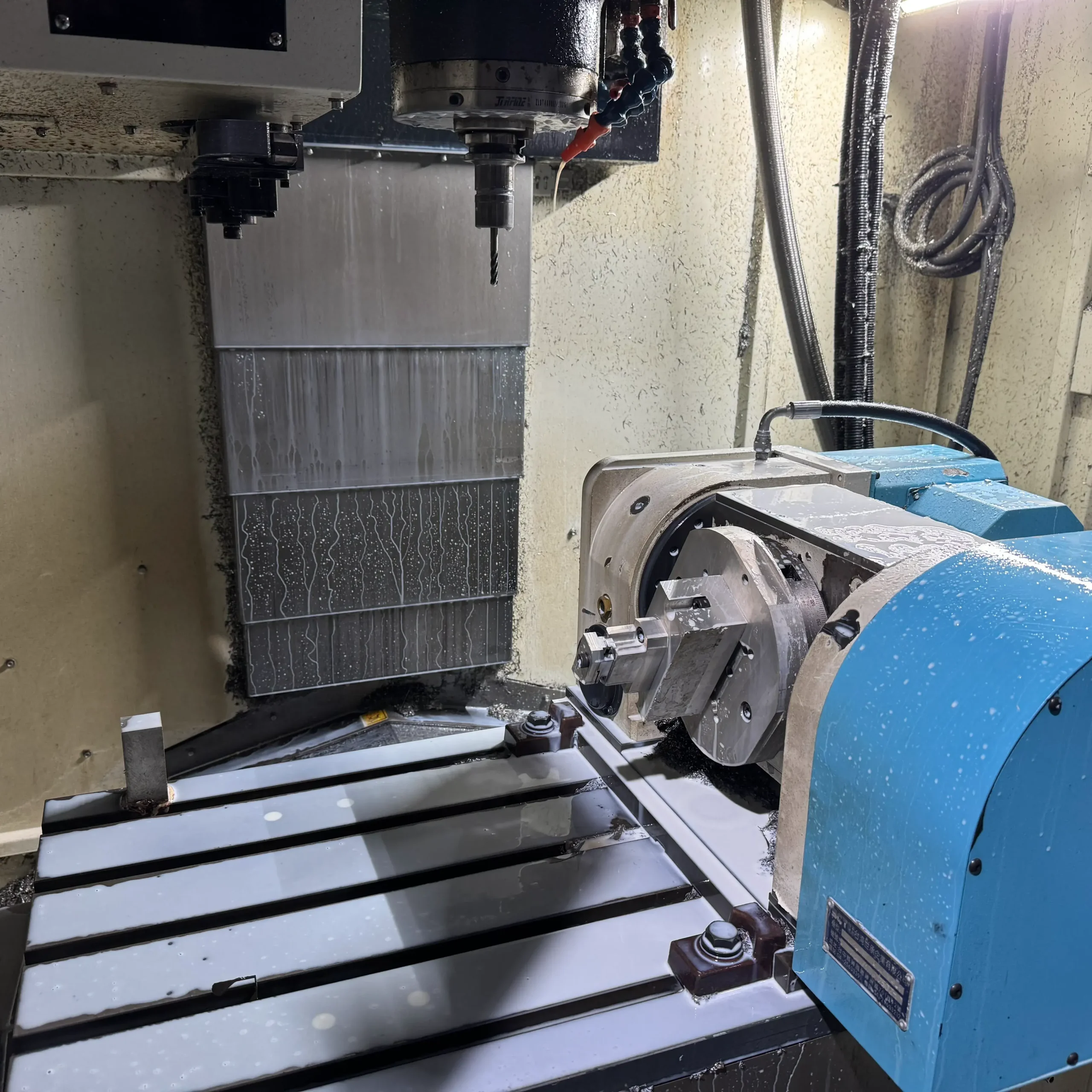
This method is particularly suitable for prismatic parts with multiple inclined surfaces, such as hydraulic valve blocks, pump housings, and machine casings. With the rotary axes locked, the machine tool’s rigidity approaches that of a static state, allowing for greater cutting depths and feed rates. When machining 316L stainless steel valve bodies, the 3+2 approach increased material removal rates by 35% compared to the proposed interpolation method, while significantly reducing tool holder vibration and greatly simplifying programming complexity.

Types of 5-Axis CNC Machine Tools

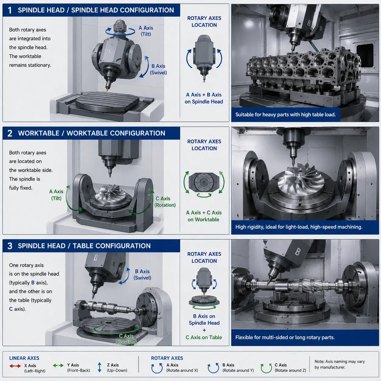
The machine tool’s structure determines its kinematic rigidity, travel limits, and the types of parts it is best suited for. Essentially, the different configurations of 5-Axis CNC Machining  are distinguished by whether the two rotary axes are located on the table side, the spindle head side, or one on each. Choosing the wrong structure for machining unsuitable parts can lead to a host of problems, including chatter, interference, and load limitations.

Spindle Head / Spindle Head Configuration

Both rotating axes are integrated into the spindle head assembly, while the worktable remains completely stationary. The primary advantage is that the worktable’s load-bearing capacity is not limited by the weight of the rotating mechanism, making it suitable for extremely heavy
Types of 5-Axis CNC Machine Tools

 workpieces, such as large marine diesel engine blocks and wind turbine gearboxes. The trade-off is rigidity, the entire swivel spindle head acts like a large cantilever, resulting in noticeable elastic deformation and low-frequency vibrations during high-angle cutting, which necessitates limiting the depth of cut.

Worktable/Worktable Configuration

Both rotary axes are located on the side of the worktable, a typical design features a cradle (tilting around the A-axis or B-axis) integrated with a C-axis rotary table. The spindle is fully fixed, offering rigidity comparable to a three-axis machine. Its dynamic characteristics are well-suited for light-load, high-speed oscillation, and the machining of small impellers and implants. A critical weakness is the overturning moment exerted by the workpiece load on the tilting axis, if the workpiece is heavy and the fixture is poorly balanced, tilting can cause the brake to slip and result in a loss of angular accuracy.

Spindle Head/Table Configuration

One rotary axis is located on the spindle head (typically the B-axis swing), and the other on the table (typically the C-axis rotation). This configuration is suitable for machining long, rotary parts or medium-sized, multi-sided workpieces, combining the flexibility of spindle swing with the indexing efficiency of table rotation. Note the coupling limitations on the range of motion of the rotary axes to avoid reaching hard stops; a full simulation must be performed using the actual machine tool kinematic model.


Advantages of 5-Axis CNC Machining

5-axis machining directly

addresses specific challenges in traditional processes caused by reference transformations, tool overhang, and cutting geometry limitations. The following are the key benefits in actual production.

Machining Complex Geometries

Only 5-axis simultaneous machining can continuously cut solid rotary parts and twisted flow channels, avoiding tool-change steps. When machining titanium alloy turbines, tilting the tool axis along the flow lines and fine-tuning the feed rate to track cutting forces allows contour deviations to be controlled within a tolerance band of +0.05/-0 mm, with no chatter marks on thin-walled sections.

Reduced Clamping Cycles

Machining all related features in a single setup eliminates reference transformation errors. For robot joint aluminum housings, switching from four setups on a 3-axis machine to two setups on a 5-axis machine improved hole-to-hole positional accuracy Cpk from 0.95 to 1.67 and reduced the scrap rate to below 0.5%.

Improve Surface Finish

Using the side edge of the tool instead of the ball-nose tip for surface finishing avoids rough surfaces caused by extrusion in the zero-speed zone at the tool tip. A 15° tilted cutting angle improved Ra from 1.6 µm to 0.4 µm, while allowing for wider step sizes and reducing machining time.

Improving Production Efficiency

Non-cutting time was significantly reduced. Auxiliary time can account for up to 35% in 3-axis machining, whereas 5-axis machining completes multiple faces in a single setup, supporting unmanned operation. The total cycle time for a stainless steel arm component was reduced from 6 hours to 3.2 hours.

Shorter Tools and Improved Stability

By tilting the workpiece or spindle, shorter tools can be used to machine deep pockets. Tool overhang is reduced by half, and deflection is reduced by a factor of eight. When machining a 400 mm deep stainless steel groove, tool overhang was reduced from 45 mm to 18 mm, tool chatter was eliminated, and tool life was extended from 15 parts to 60 parts.

Looking for high-precision 5-axis machining services?

When Should 5-Axis CNC Machining Be Used?

The decision should be based on the functional requirements for precision and the strict demands for geometric accessibility of the part’s features, rather than technical preferences. The following scenarios represent clear engineering drivers.

Complex Curved Parts

Continuous-curvature surfaces, such as impellers and bio-conformal surfaces, must be machined smoothly along spatial curves to avoid tool-to-surface steps. 5-axis simultaneous machining maintains a constant tool axis angle, meeting contour accuracy requirements.

Deep Cavities and Chamfers

For cavities deeper than four times the tool diameter, or mold cooling cavities with undercuts, 3-axis tools cannot reach the root. 5-axis machining allows the tool to be tilted to clear the root, generating a continuous path without leaving any steps.

Multi-surface Precision Parts

For housings and manifolds with multiple surfaces featuring hole patterns, slots, and sealing surfaces that require strict positional accuracy, 5-axis machining in a single setup ensures a unified reference, significantly improving consistency in precision and reducing scrap rates.

High-Precision Parts

For parts with IT5–IT6 tolerances, geometric tolerances under 0.01 mm, and features distributed across multiple surfaces, 5-axis machining allows for concentrated finishing in a single continuous operation. Real-time compensation via in-process measurement prevents clamping errors from eroding the tolerance band.

Prototyping and Small-Batch Production

Investing in dedicated fixtures is not cost-effective for prototypes and small batches. With 5-axis machining using universal clamps and suction cups for rapid setup, the manufacturing time for aluminum alloy transmission prototypes has been reduced from three weeks to five days, without a significant increase in cost.

What materials can 5-axis CNC machines machine?

Material behavior directly affects tool selection, cooling strategy, cutting stability, and machining efficiency in 5-axis CNC machining. Different materials require different toolpaths, cutting parameters, and heat control methods to maintain dimensional accuracy and surface quality.

MaterialCommon GradesTypical Machining Challenges5-Axis Machining Strategy
Aluminum6061, 6063, 7075, 2024, 5052Deformation, built-up edge, stress releaseSymmetrical roughing, polished carbide tools, air blast or alcohol mist cooling
Stainless Steel303, 304, 304L, 316, 316L, 17-4PHWork hardening, chip evacuation, heat buildupPeck drilling, full chip evacuation, stable cutting parameters
TitaniumTi-6Al-4V (Grade 5), Grade 2, Grade 23Heat concentration, springback, poor thermal conductivityDynamic toolpaths, small engagement angle, controlled cutting heat
Copper & BrassC101, C110, H59, H62, Brass 360Built-up edge, chip adhesionTool tilt to increase effective rake angle and improve chip evacuation
Engineering PlasticsPEEK, Ultem, Delrin (POM), Nylon, PTFE, PCThermal deformation, weak rigidity, melting riskLight clamping force, compressed air cooling, thin-chip cutting strategy

Industries Utilizing 5-Axis CNC Machining

The driving factors for 5-axis machining vary across different industries. The aerospace sector prioritizes overall structural strength and weight reduction, while the medical field emphasizes clean surfaces and contour accuracy, and the automotive industry pursues efficiency and consistency.

In the aerospace sector, structural frames, disk blanks, turbine blades, and engine casings require thin-walled designs, high contour accuracy, and surface integrity when machined from high-temperature alloys and titanium alloys. Integrated machining on 5-axis machines eliminates assembly errors and minimizes stress concentration to improve fatigue life.

In the medical device sector, products such as knee joint systems, spinal fusion devices, and surgical guides are made from materials including Ti6Al4V ELI, CoCr, and PEEK. Key requirements include surfaces that conform to bone contours without sharp edges. 5-axis finishing achieves this in a single operation, preventing post-polishing alterations to the prosthesis’s bone-contacting surface geometry.

In the automotive industry, high-performance powertrains, electric race car inverter housings, and lightweight chassis components require consistency in high-volume production and rapid manufacturing cycles. 5-axis machining is primarily used to eliminate the setup time associated with multiple re-clamping operations, completing the entire machining process within a single automated cell.

The energy sector involves gas turbine and steam turbine components, well control valve bodies, and solar heliostat mounts. Twist blades and complex internal flow channels made of high-temperature nickel-based alloys are typical examples of 5-axis machining. These present immense cutting challenges, with a single impeller potentially requiring dozens of tools.

In the defense sector, weapon sight mounts, missile guidance frames, and optical stabilization platforms often utilize high-strength aluminum, titanium, and Invar alloys, which demand long-term dimensional stability. 5-axis machining ensures that the relative positional error between optical axis mounting brackets is less than 5 arcseconds.

In robotics and automation, the machining of robotic arm linkages and harmonic drive idler wheels involves substantial material removal (sometimes up to 90%) and requires uniform wall thickness to prevent dynamic imbalance. 5-axis machining, which involves cutting around the blank, allows for the symmetrical release of residual stresses, thereby maintaining post-machining geometric stability.

FAQ about 5 axis CNC machine tools

3-axis CNC machining can only cut from fixed directions, requiring multiple setups to complete multi-surface machining. 5-axis CNC machining allows the tool or workpiece to be tilted, enabling the machining of multiple surfaces and features at various angles in a single setup.

It does not automatically produce higher precision, but rather creates the conditions for greater consistency by eliminating errors from multiple reference transformations, using shorter tool lengths, and performing concentrated finishing in a single setup. Achieving high precision still depends on machine calibration and process design.

These include twisted blades, monolithic flow channels, undercut features, hole patterns with complex angular arrangements, or single parts with strict relative geometric tolerances on multiple surfaces. Specific examples include turbine blades, skeletal implants, and hydraulic manifolds.

When the part’s surface must be machined by the tool following a continuous vector path tangentially to the surface, or when the tool must constantly change its orientation to avoid interference in deep areas. If only corner chamfers need to be machined, 3+2 positioning is sufficient.

For complex parts with multiple surfaces, it typically reduces overall manufacturing costs by minimizing fixture investment, shortening turnaround time, and reducing scrap. However, for simple flat parts, it does not lower the hourly labor rate.

Table of Contents
Discuss Your Complex Machining Requirements

Need Custom CNC Machined Parts?

From rapid prototypes to low-volume production, our engineering team can review your drawings and provide a manufacturing quote.

  • 24-Hour Quotation
  • DFM Engineering Support
  • No Minimum Order
  • ISO 9001 Certified
Request A Quote
Upload your drawing and get a quote within 24 hours.
