


In CNC machining, even if the machine tool has very high precision, runout in the cutting tool or workpiece during rotation can still lead to dimensional deviations, poor surface roughness, reduced tool life, and even affect the consistency of an entire batch of parts.
Runout is not a specific machining process, but rather a type of rotational error. It can originate from various components, including the spindle, tool holder, collet, cutting tool, or clamping method, and is therefore one of the key parameters to control in precision machining.
This article will explain what runout is, its causes, its impact on CNC machining, how to measure it, and how to reduce it, to help you better understand this key machining parameter.
What Is Runout in Machining?
Runout refers to the error caused by the deviation of the actual rotational path of a cutting tool or workpiece from the theoretical rotational center during rotation.
Ideally, the cutting tool should rotate stably around the spindle center, maintaining the same motion path at every point;
However, when runout is present, the cutting tool will exhibit slight oscillation or eccentric rotation, causing the cutting path to deviate.
Why Runout Occurs
Runout is essentially a form of eccentricity in a rotating system and does not necessarily indicate machine tool damage.
It may be caused by a combination of factors, such as:
- Insufficient spindle accuracy
- Wear on the tool holder or collet
- Tool deflection
- Contaminants in the spindle taper bore
- Improper clamping
Why Is Runout Important in CNC Machining?
Many people believe that runout in the range of tens of micrometers has little impact, but in reality, during high-speed and precision machining, runout often exacerbates various machining issues.
When a cutting tool experiences runout, not every cutting edge bears the same cutting load; instead, some edges cut more material while others cut too little, which leads to a decline in machining quality.
Common effects include:
- Reduced dimensional accuracy of parts
- Larger hole diameters or increased positional errors
- Worse surface roughness
Accelerated tool wear - Vibration (chatter) during machining
- Shorter tool and spindle life
- Higher scrap rates and rework costs
For the aerospace, medical device, mold, and precision parts manufacturing industries, controlling runout is often key to ensuring machining stability.

Common Types of Runout in Machining
Runout is typically classified into two types based on the direction of deviation.
Radial Runout
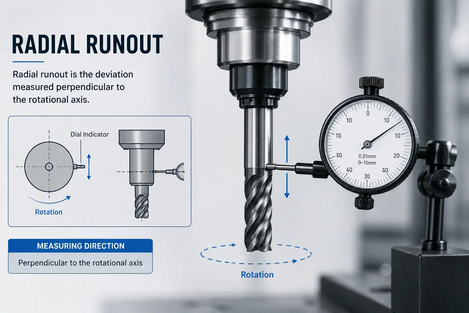
Radial runout is the most common type.
It refers to the deviation of a cutting tool or workpiece from the center of rotation in the radial direction, causing the rotational path to form an eccentric circle.
This condition typically affects:
- Bore diameter
- Outer diameter
- Concentricity
- Surface roughness
Axial Runout
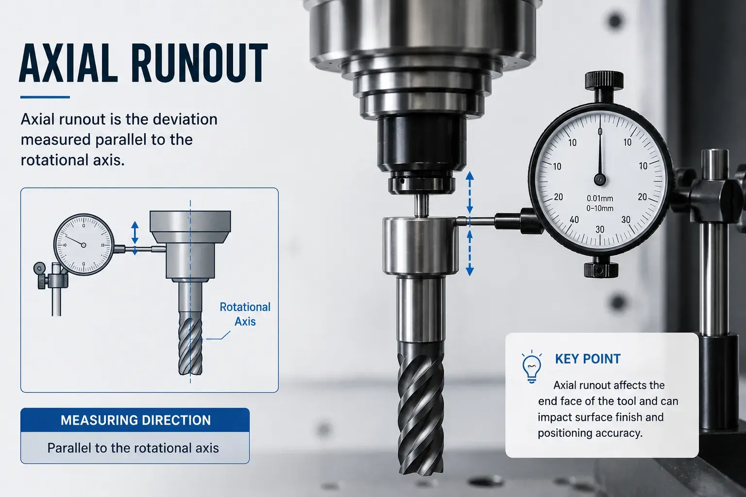
Axial runout refers to the up-and-down oscillation of the tool face along the spindle axis.
It primarily affects:
- Face flatness
- Cutting depth
- Milling surface quality
- Face machining accuracy
Compared to radial runout, axial runout has a greater impact on face machining and positioning accuracy.
How Does Runout Occur?
Runout is often not caused by a single factor, but rather results from the combined effects of multiple machining processes.
| Cause | Effect on Machining |
|---|---|
| Dust or chips in the spindle taper | Causes the tool holder to be mounted off-center |
| Worn tool holder | Reduces concentricity |
| Worn collet | Makes tool clamping unstable |
| Bent cutting tool | Shifts the cutting path |
| Worn spindle bearings | Reduces stability during high-speed rotation |
| Improper clamping | Increases overall eccentricity |
Therefore, in actual production, even if the machine tool itself has very high precision, significant runout can still occur if the toolholder, collet, or clamping procedures are not properly managed.
How to Measure Runout?
Runout is typically measured using a dial indicator in conjunction with a standard test bar or cutting tool. This is the most common and reliable inspection method in CNC machining.
During the measurement process, the dial indicator is used to detect radial or axial deviations produced by a rotating component over one full revolution, thereby determining whether the cutting tool, tool holder, or spindle exhibits runout.
The general measurement steps are as follows:
Step 1: Install the Test Bar or Cutting Tool
Securely mount the standard test bar or the cutting tool to be inspected onto the spindle or toolholder, ensuring the mounting configuration matches the actual machining conditions to obtain more accurate measurement results.
Step 2: Adjust the Dial Indicator Position
Secure the dial indicator to a magnetic base or other stable mount so that the stylus lightly contacts the surface of the test bar, maintaining an appropriate amount of preload to prevent the stylus from slipping or being subjected to excessive force.
Step 3: Slowly Rotate the Spindle
With the spindle power turned off, slowly rotate the spindle by hand through a full revolution (or rotate at a low speed as specified by the equipment). Observe the changes in the dial indicator’s reading and record the maximum and minimum values throughout the entire rotation.
Step 4: Calculate TIR (Total Indicated Runout)
The difference between the maximum and minimum readings is called TIR (Total Indicated Runout), which is the most commonly used metric for evaluating runout. Generally, the smaller the TIR value, the higher the rotational accuracy of the cutting tool or workpiece, and the better the machining stability.

Tip: Before measuring runout, always clean the spindle taper, tool holder, and test bar. Even small chips or dust can affect the measurement and lead to inaccurate results.
What is the typical allowable runout during machining?
There is no single standard that applies to all machining scenarios; the allowable runout varies depending on machining accuracy, tool size, and machine tool performance.
The following table provides general guidelines:
| Machining Type | Recommended Runout |
|---|---|
| General CNC Machining | ≤0.02 mm |
| Precision Milling | ≤0.01 mm |
| High-Speed Machining | ≤0.005 mm |
It is important to note that the values above are only common industry references; the actual allowable range should be determined based on a combination of part tolerance requirements, tool length, toolholder quality, and the material being machined.
How to Reduce Runout in CNC Machining?
Runout cannot usually be completely eliminated, but through proper equipment maintenance, tool management, and clamping methods, it can be controlled within reasonable limits, thereby improving machining accuracy, enhancing surface quality, and extending tool life.
The following are several common methods for reducing runout in CNC machining.
Keep the Spindle Bore and Tool Holder Clean
Dust, chips, or oil residue on the spindle bore, tool holder, and clamping surfaces can prevent the tool holder from seating fully against the spindle, resulting in an eccentric fit.
Therefore, cleaning the contact surfaces before each tool change to ensure accurate tool holder positioning is one of the simplest and most effective ways to reduce runout.
Regularly Inspect and Replace Worn Collets and Tool Holders
Collets and tool holders can become worn or deformed over time, leading to a decrease in clamping force and causing the tool to wobble during high-speed rotation.
Regularly inspect the clamping system for wear and promptly replace damaged components to help maintain stable concentricity and machining accuracy.
Use High-Precision Toolholder Systems
High-quality toolholders typically feature higher manufacturing precision and better dynamic balance, effectively reducing tool mounting errors.
For high-speed machining or high-precision parts, selecting a precision toolholder system can significantly reduce runout and improve machining stability.
Reduce Tool Overhang
The longer the tool overhang, the lower the rigidity, making it more prone to deflection and vibration under cutting forces.
Provided that machining requirements are met, minimizing tool overhang as much as possible can improve overall rigidity and reduce the impact of runout on machining quality.
Regularly Check Spindle Accuracy
Even when using high-quality tools and toolholders, significant runout can occur if the spindle itself is worn or has bearing play.
Therefore, a dial indicator should be used regularly to check spindle runout, allowing for the timely detection and resolution of equipment accuracy issues to prevent them from affecting subsequent machining.
Check Runout After Each Tool Installation
For high-precision machining projects, relying solely on experience when mounting tools is insufficient.
Using a dial indicator to quickly check the runout value after tool installation allows for the timely detection of clamping anomalies, thereby preventing dimensional deviations, reduced surface quality, or abnormal tool wear caused by tool eccentricity.
How to Determine if Runout Is Present During Machining?
In actual production, runout does not alert operators directly like a machine alarm; instead, it gradually becomes apparent through the machining results. Therefore, when part quality suddenly deteriorates, runout is often one of the first factors engineers need to investigate.
If any of the following situations occur during machining, you should consider checking for runout:
Unstable Hole Diameter
If the machined hole diameter fluctuates between larger and smaller sizes, or if holes machined using the same program exhibit poor dimensional consistency, this may indicate that the cutting tool is moving eccentrically during rotation. Runout causes the actual cutting path of the tool to deviate, resulting in oversized holes or reduced roundness.
Sudden Deterioration in Surface Roughness
When the tool experiences runout, the cutting load distributed across each cutting edge is uneven, which can easily leave irregular tool marks or ripples on the workpiece surface, causing a noticeable deterioration in surface roughness. Even if the cutting parameters remain unchanged, a decline in machining quality may still occur.
Abnormal Vibration or Noise During Machining
Excessive runout disrupts the rotational balance of the tool, making it more prone to vibration (chatter) and abnormal noise during high-speed machining. This not only affects machining stability but may also accelerate wear on the tool and spindle.
Significantly Shortened Tool Life
Under normal conditions, a multi-edge tool should participate in the cutting process evenly. However, when runout is present, certain cutting edges bear a greater cutting load, causing them to wear significantly faster than others. This shortens the overall tool life and increases the frequency of tool changes.
Uneven Tool Marks or Abnormal Cutting Traces
If the workpiece surface exhibits tool marks of varying depths, periodic ripples, or obvious cutting traces, it is highly likely that the tool is experiencing slight wobble during rotation. This phenomenon is particularly noticeable during high-speed milling and precision machining.
Decreased Part Machining Consistency
When multiple parts are machined consecutively on the same machine tool using the same program, if dimensions gradually change or consistency between different batches decreases, runout should be checked. In mass production, even very small runout errors can be amplified as the number of parts machined increases, ultimately affecting product yield.
How YUANYI Controls Runout in Precision CNC Machining
In precision CNC machining, consistent machining quality depends not only on advanced equipment but also on strict control of every stage of the machining process.
At YUANYI, we minimize the impact of runout on part precision through standardized machining processes and comprehensive quality control.
From tool clamping and spindle accuracy checks to post-machining dimensional verification, every step is carried out in accordance with established specifications and verified using inspection equipment such as dial indicators and CMMs.
For most precision parts, we can achieve machining tolerances of ±0.005 mm and, based on project requirements, provide 100% dimensional inspection, inspection reports, and material certificates to help customers achieve consistent and stable machining quality.
Need High-Precision CNC Machining?
Send us your CAD file or drawing. YUANYI provides precision CNC machining with ±0.005 mm tolerance, 100% dimensional inspection, and fast engineering support.
Get a QuoteConclusion
Runout may seem like nothing more than a slight deviation caused by the rotation of a cutting tool or workpiece, but it directly affects the dimensional accuracy, surface quality, tool life, and product consistency of CNC machining. For parts with tight tolerance requirements, even minimal runout can lead to a decline in machining quality or even render parts unusable.
By understanding the causes of runout, mastering proper measurement methods, and ensuring proper tool clamping, spindle maintenance, and quality inspection during the machining process, most runout issues can be effectively controlled. Whether in prototype development or mass production, stable control of runout is a crucial foundation for achieving high-precision CNC machining.
Frequently Asked Questions
Runout measures how much a rotating tool or workpiece deviates from its true axis during rotation, while concentricity describes how closely two or more circular features share the same center. In simple terms, runout is a measurement taken during rotation, whereas concentricity is a geometric relationship between features.
The acceptable runout depends on the machining operation and required tolerance. As a general guideline, many precision machining applications aim for 0.01 mm or less, while high-speed machining may require even tighter control.
Spindle speed does not create runout, but higher spindle speeds can amplify its effects. Even a small amount of runout may lead to greater vibration, reduced surface finish, and faster tool wear during high-speed machining.
Hard-to-machine materials such as titanium, stainless steel, and nickel-based alloys are generally more sensitive to runout because they generate higher cutting forces and require greater machining stability. Controlling runout is especially important when machining these materials.
Yes. Excessive runout changes the amount of material removed by each cutting edge, often leaving visible tool marks, uneven cutting patterns, and a rougher surface finish.
No. It is almost impossible to eliminate runout entirely because every machining system has some level of manufacturing and assembly tolerance. The goal is to keep runout within an acceptable range for the specific machining application.



