
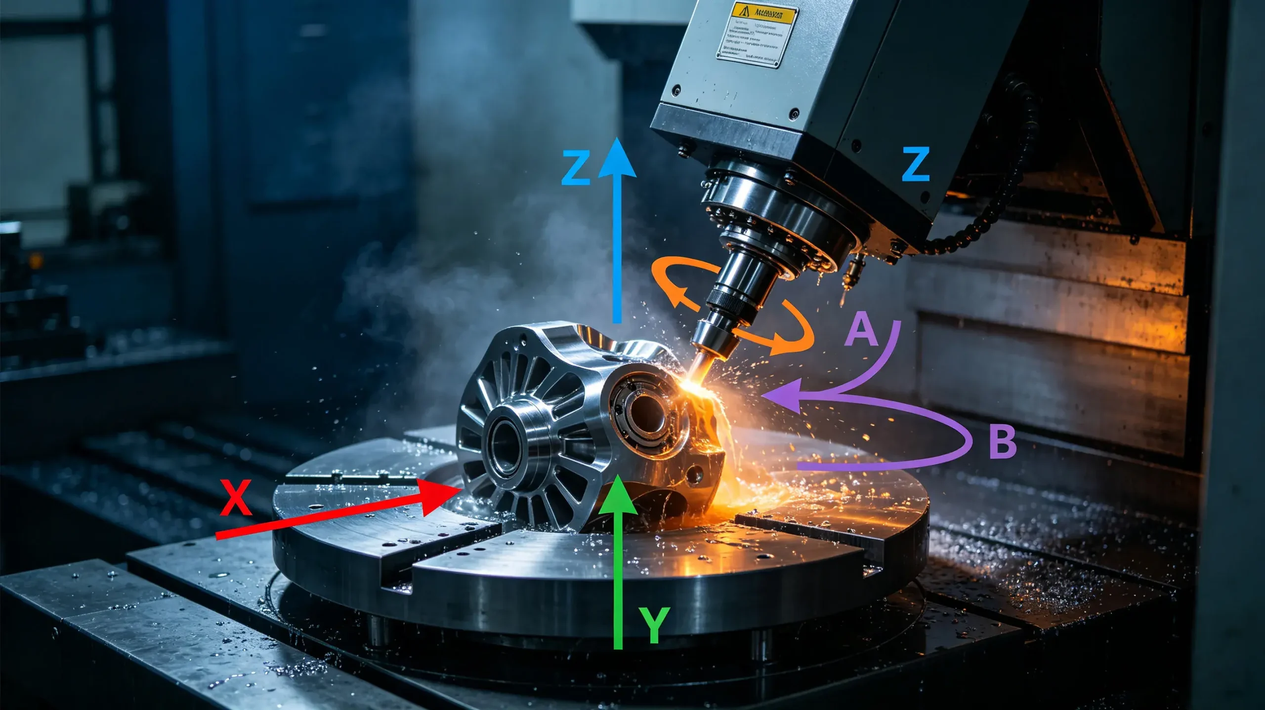
What Are the 5 Axis on a CNC Machine? X, Y, Z, A and B Axis Explained

5 Axis on a CNC Machine

Walk into any manufacturing workshop equipped with a 5-axis machining center, and you’ll hear engineers discussing how “5-axis simultaneous machining” has easily solved the problem of repeated setup required in the 3 axis era. However, for many designers and procurement professionals, exactly which five axis are involved—and how the A and B axes actually rotate—remains a vague concept.

This article will explain, in simple and easy-to-understand terms, the principles of motion, common configurations, and practical machining benefits of the three linear axes (X, Y, and Z) and the two rotary axes (A and B) on a 5-axis CNC machine. After reading it, you’ll discover that five-axis machining is not simply a matter of “adding two rotary axes”—it fundamentally changes the machining process for parts.

Understanding CNC Machine Axis

In CNC machining, an “axis” represents a controlled direction of motion—which can be linear movement or rotation around a specific axis. Each axis has a standard letter designation, and this naming convention is derived from the Cartesian coordinate system. The machine tool’s control system coordinates the movements of each axis to position the cutting tool relative to the workpiece with extremely high precision.

When we say a machine tool is “5-axis,” it means it can simultaneously control five independent degrees of freedom. This not only expands geometric capabilities but also influences engineers’ overall approach to fixture design, toolpath planning, and final precision.

What Are the Three Basic Axis in CNC Machining?

It all starts with three basic linear axis. Once you understand them, adding rotational axis on top of them is a natural progression.
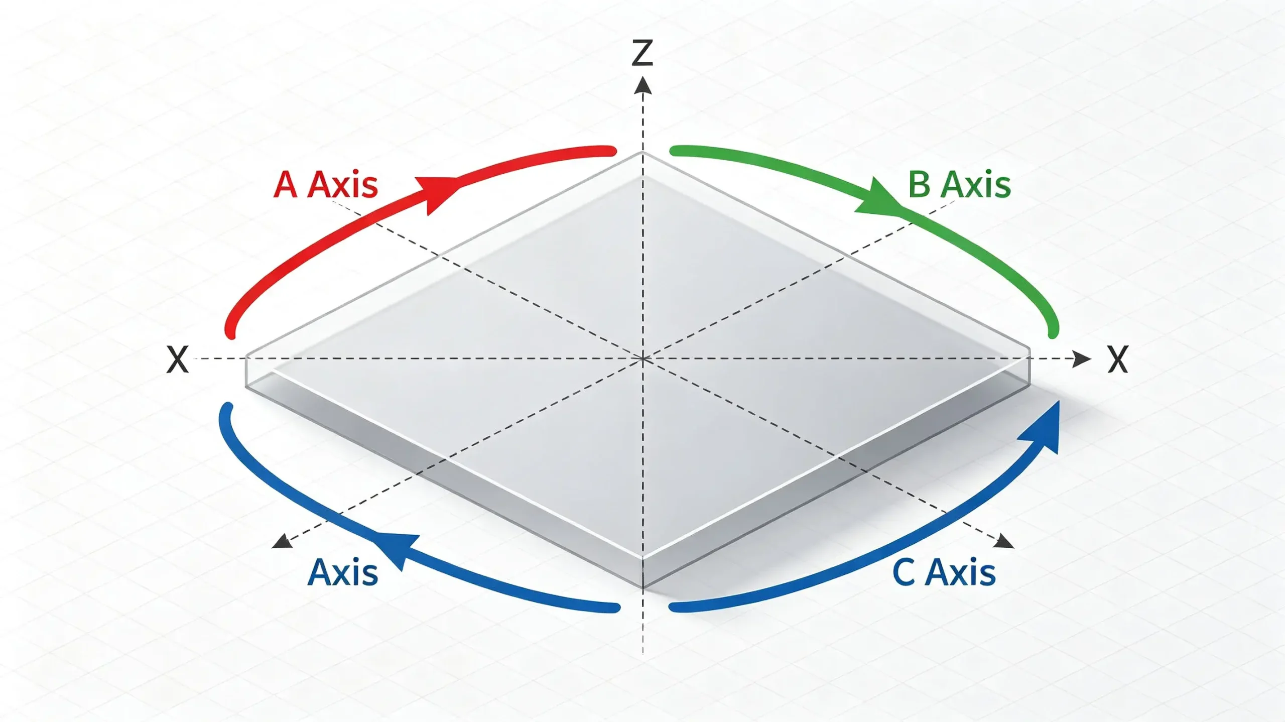
Three Basic Axes in CNC Machining

X Axis: Horizontal Movement

The X-axis typically controls the left-to-right movement of the worktable in the horizontal plane. For vertical machining centers, the X-axis has the longest travel and handles the primary feed motion in the horizontal direction. When you need to mill a straight contour along the length of a workpiece, the X-axis is the primary axis driven by the program.

Y Axis: Depth Movement

The Y-axis controls the worktable’s movement back and forth, determining the tool’s “depth” of cut into the workpiece. The combined movement of the X and Y axis defines any two-dimensional path perpendicular to the spindle centerline plane; for example, milling a cavity or cutting a curved groove both rely on interpolation in the XY plane.

Z Axis: Vertical Movement

The Z-axis controls the up-and-down movement of the spindle, which actually determines how deeply the tool cuts into the material. On a vertical milling machine, the Z-axis brings the tool into the workpiece; on a horizontal milling machine, the Z-axis moves the tool toward the column. The accuracy of the Z-axis directly affects the surface finish of the part’s bottom surface and the consistency of feature depths across multiple parts.

What Are the Extra Axis on a 5-Axis CNC Machine?

In addition to the three linear axis, five-axis machine tools incorporate rotational axis that allow the tool or workpiece to be tilted. The rotational axis are named according to the right-hand rule: the axis rotating around the X-axis is called the A-axis, the axis rotating around the Y-axis is called the B-axis, and the axis rotating around the Z-axis is called the C-axis.
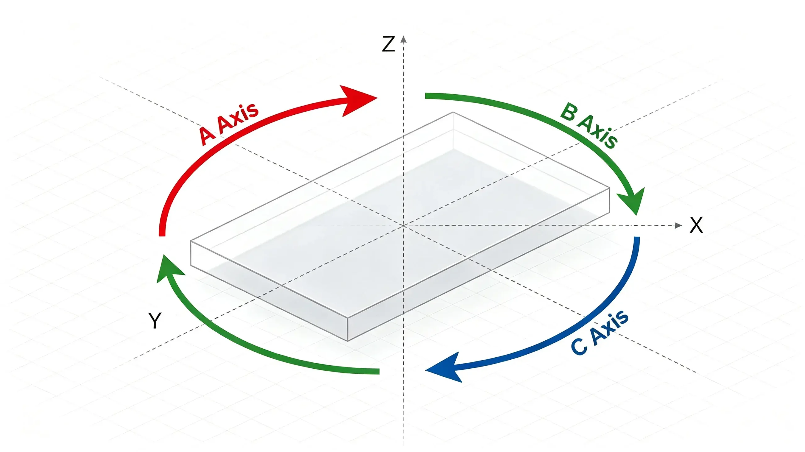
5-Axis CNC Machine

A Axis: Rotation Around the X Axis

The A axis rotates around the X axis. On “ear-type” five-axis machines, this typically takes the form of a tilting table that tilts the workpiece toward or away from the spindle. Imagine a horizontally clamped cylinder rotating around its own axis—that is the A-axis motion. It can machine features on the cylindrical surface or allow the tool to cut into the top of the workpiece at a specific angle.

B Axis: Rotation Around the Y Axis

The B-axis rotates around the Y-axis. In polyhedral machining, the B-axis is responsible for swiveling the tool or table left and right. Some machines integrate the B-axis into the spindle head, forming a “swivel head” configuration that allows the tool to sweep across the sides and undercuts of the workpiece without the need for re-clamping.

C Axis: Rotation Around the Z Axis (Optional)

The C-axis rotates around the Z-axis and is typically found on mill-turn or five-axis machining centers equipped with a rotary table. It allows the table itself to perform circular feed, making it suitable for machining cylindrical surfaces, end-face grooves, or performing polar coordinate interpolation. Although, strictly speaking, a complete five-axis system does not necessarily include the C-axis, in practical configurations, the C-axis often appears in combination with the A or B axis.

What Are the Different 5-Axis CNC Machine Configurations?

Not all five-axis machine tools have the same motion allocation. Based on the combination of rotary axis, there are three common classic configurations.
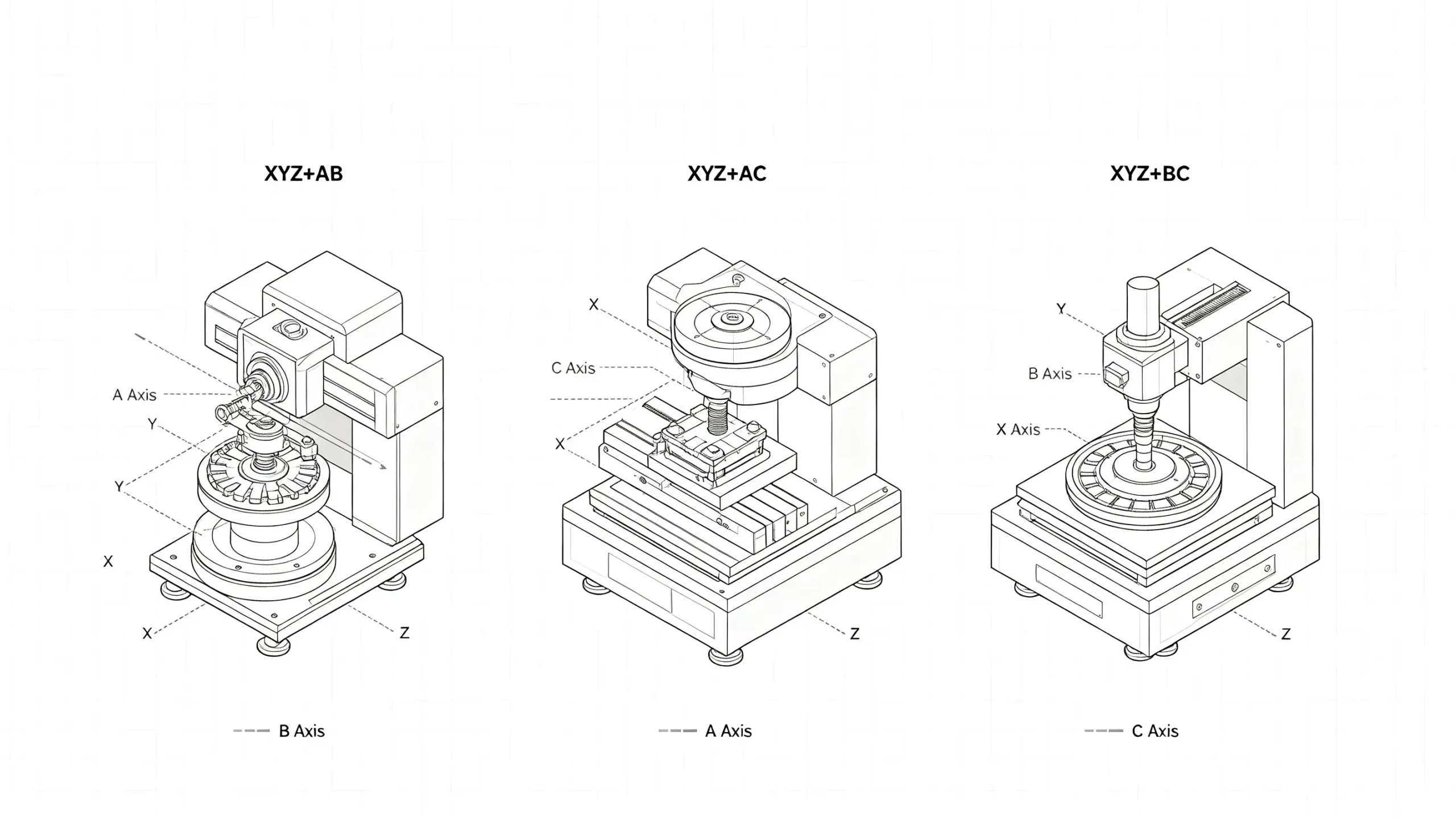
5-Axis CNC Machine Configurations

XYZ + AB Configuration

In this configuration, the linear axis X, Y, and Z remain unchanged, while the two rotary axis are A (rotation around the X-axis) and B (rotation around the Y-axis). Typical structures include a dual-tilting table or a combination of one tilting head and one tilting table. The workpiece tilts on the A-axis and swivels on the B-axis, while the spindle performs only linear motion. This configuration offers high rigidity and is suitable for machining small- to medium-sized complex parts, such as aerospace hydraulic valve bodies.

XYZ + AC Configuration

This is the common “tilting spindle plus rotary table” configuration. The A-axis tilts the entire tilting spindle, while the C-axis rotates the table in the horizontal plane. The advantage is that the bottom of the workpiece is always supported, which is beneficial for machining long, slender, or flat parts, and facilitates five-side machining—allowing the top and four sides to be machined in a single setup.

XYZ + BC Configuration

In this configuration, the rotating axis are the B and C axis. It is commonly found in large gantry or horizontal machining centers where the spindle features a B-axis tilt and the worktable features a C-axis rotation. The B-axis tilts the tool, while the C-axis rotates the workpiece. This configuration is particularly suitable for large housings, engine casings, and other parts that require drilling and tapping at multiple angles.

How Do the 5 Axis Work Together in CNC Machining?

The true advantage of a five-axis system lies in “interpolation.” Rather than rotating the tool separately after the three linear axis have completed their movements, all axis move in a coordinated manner simultaneously. For example, when machining an aerospace impeller, the tool must not only follow the curvature of the blade surface (requiring continuous changes in the X, Y, and Z axis) but also constantly maintain the optimal angle between the tool axis and the surface normal (with axis A and B tracking in real time). During this process, the CNC controller performs hundreds or even thousands of interpolation calculations per second to ensure a smooth, interference-free toolpath.
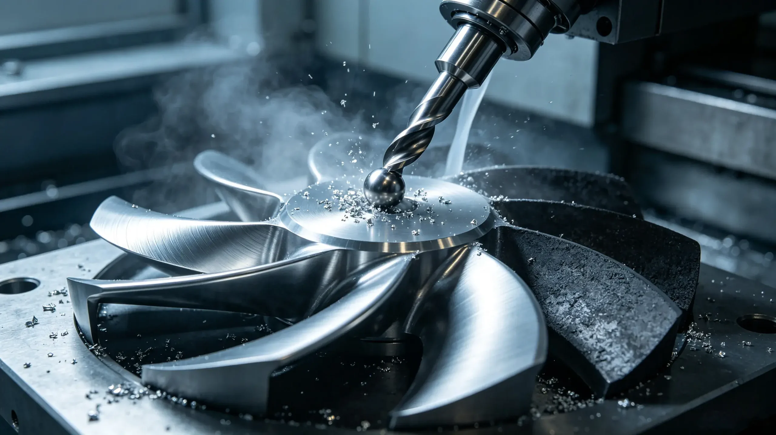
Five Axes Work Together in CNC Machining

In CAM software, after an engineer sets the machining strategy, the post-processor converts these instructions into axis motion codes specific to the machine tool. The end result is that the tool tilts to avoid non-machining areas of the workpiece while precisely cutting into the designed surface—all completed in a single setup.

Why Are the Additional Axes Important in 5-Axis Machining?

Having two additional axes of rotation is about more than just “milling a bevel.” They bring substantial improvements in capability at the engineering and manufacturing levels.

Machining Complex Geometries

With the A and B axes, the tool can approach the workpiece surface from any angle, directly machining complex shapes that 3 axis machines—even with specialized fixtures—cannot achieve—such as free-form surfaces, lateral bosses inside deep cavities, and twisted cooling holes. This greatly expands designers’ geometric freedom, eliminating the need to sacrifice performance out of concern for “machinability.”

Reducing Multiple Setups

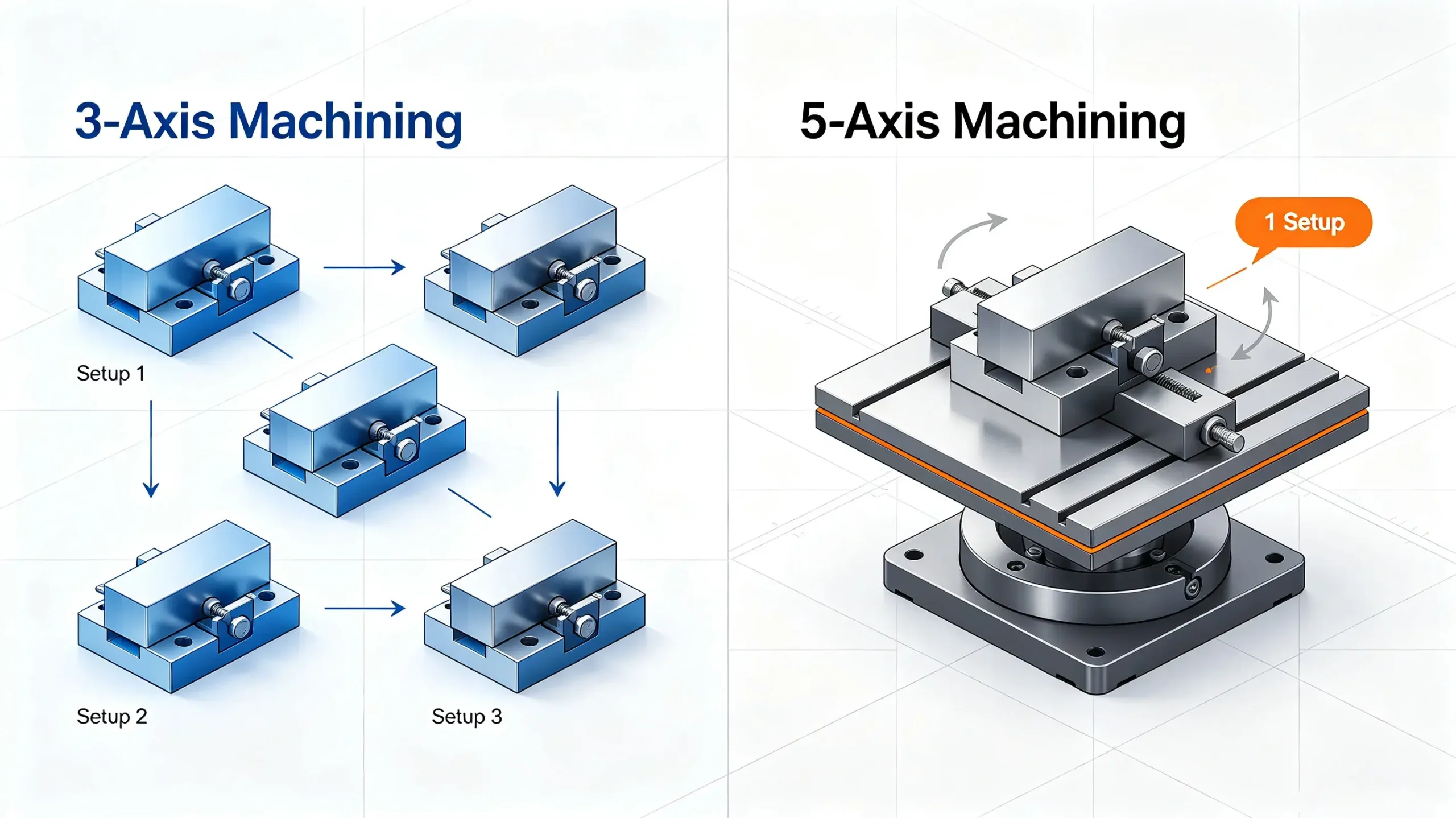
Machining a polyhedral part on a 3-axis machine may require flipping and re-clamping the workpiece three times or more. Each re-clamping introduces positioning errors and consumes a significant amount of labor time. Five-axis machining requires only a single setup to complete milling, drilling, and tapping on the top, side, and inclined surfaces, not only saving the cost of multiple fixtures but also avoiding accuracy losses caused by repeated positioning.

Improve Accuracy and Surface Finish

Reducing the number of setups directly shortens the tolerance chain. At the same time, five-axis machining allows the use of short-fluted cutting tools, as the tool can be tilted to avoid interference between the shank and the workpiece. Short tools offer greater rigidity and produce less machining vibration, resulting in lower surface roughness and longer tool life. These advantages are particularly evident for parts that require extremely high surface and dimensional consistency, such as mold cavities and optical mirror mounts.

5-Axis CNC vs 3-Axis CNC Machining: What Is the Difference?

5-Axis CNC vs 3-Axis CNC Machining

The most fundamental difference between the two lies not in accuracy itself, but in manufacturing capabilities and process efficiency.

Comparison Factor3-Axis CNC Machining5-Axis CNC Machining
Degrees of FreedomX, Y, and Z three linear axesX, Y, Z linear axes plus two rotary axes (typically A/B or A/C)
Number of SetupsMultiple setups are often required for multi-sided machiningMost complex parts can be machined in a single setup
Tool AccessibilityLimited to vertical or fixed cutting anglesAllows angled tool access for undercuts, deep cavities, and complex features
Geometric CapabilityLimited for freeform surfaces and multi-angle featuresExcellent for complex surfaces, blades, and irregular cavities
Fixture RequirementsComplex parts may require multiple dedicated fixturesReduces fixture complexity and may use standard workholding solutions
Accuracy RetentionMultiple setups can introduce accumulated positioning errorsSingle-setup machining reduces tolerance stack-up and improves positional accuracy
Surface QualitySurface finish depends on ball-end mill step-over and may produce visible tool marksOptimized tool angles improve cutting efficiency and create more consistent surface finishes
Typical ApplicationsSimple brackets, flat components, and high-volume dedicated partsAerospace components, medical implants, complex molds, impellers, and precision parts

It should be noted that 3-axis machine tools still offer a cost advantage when machining simple shapes or high-volume parts that require a single machining operation. The choice of process depends on the part’s complexity and quality requirements, rather than simply assuming that five-axis machining is “better.”

Applications of 5-Axis CNC Machining

The application of five-axis machining has penetrated virtually every industry with stringent requirements for part performance and integration:

  • Aerospace: Turbine blades, integral blisks, and airframe structural frames—these parts require machining of titanium alloys or superalloys and feature complex geometries, making five-axis machining virtually indispensable.
  • Medical Devices: Orthopedic knee implants, surgical guides, and pacemaker housings feature complex curved surfaces and extremely high surface finish requirements. Five-axis machining completes these parts in a single operation, eliminating the risk of contamination from multiple setups.
  • Automotive Molds: Headlight molds and intake manifold mold cavities often feature deep cavities and narrow slots, requiring tools to be tilted for root clearance. Five-axis machining can access corners that 3-axis machining cannot reach.
  • Precision Robotics: Joint motor mounts and harmonic reducer flexible wheels require precise multi-angle hole patterns and consistent wall thickness; five-axis machining efficiently ensures positional accuracy.
  • Energy and Fluid Equipment: Impellers, volutes, and internal intersecting flow channels in valve bodies—five-axis machining produces smooth, flowing internal cavity surfaces, enhancing fluid efficiency.

Conclusion

The true value of five-axis CNC machining lies not in the machine tool having two additional rotational axes, but in the fact that it has completely transformed the way engineers plan toolpaths. Machining multiple surfaces in a single setup means shorter tolerance chains, simplified fixturing, and faster iteration—all of which ultimately translate into improved part quality, faster delivery times, and lower project costs.

Understanding the respective roles of the X, Y, and Z axes, as well as the A and B axes, and the appropriate applications for the three common configurations will help you make more informed manufacturability decisions during the part design phase, rather than discovering after the drawings have been released that “this feature cannot be machined with a three-axis machine.”

Need Precision 5-Axis CNC Machining for Complex Parts?

Understanding the X, Y, Z, A and B axes is only the first step. For real production, the right machining strategy, fixture design, tool path planning, and inspection process all affect part accuracy, surface finish, and delivery time. YuanYi helps you turn complex designs into high-precision CNC machined parts with stable quality.

✓ 5-Axis Machining
✓ Tight Tolerances
✓ Complex Geometry
✓ 100% Inspection

Frequently Asked Questions

Not every part requires 5-axis machining. It becomes cost-effective when a part needs multiple setups, complex angles, deep cavities, or difficult-to-reach features. By reducing fixtures, setup time, and positioning errors, 5-axis machining can lower the total production cost for complex parts.

3+2 machining uses rotary axes to position the part at a fixed angle, then cuts with standard X/Y/Z movements. 5-axis simultaneous machining moves all axes together, allowing continuous tool movement along complex surfaces. 3+2 is ideal for angled features, while true 5-axis is better for freeform surfaces and complex geometries.

Modern 5-axis machines use features like dynamic work offsets and tool center point control (TCP). The CNC system automatically compensates for rotary movements, allowing programmers to work directly from the 3D model without manually calculating position changes after tilting the part.

A high-quality 5-axis machining center can typically achieve tolerances within ±0.001 mm for many precision parts. However, accuracy depends on machine condition, calibration, temperature control, and part size—not just the machine specifications.

Yes. 5-axis machining is widely used for engineering plastics such as PEEK, Delrin, and polycarbonate, especially for parts with complex surfaces or multiple angles. Proper cutting parameters and fixturing are important because plastics can deform more easily than metals.

5-axis programming usually takes longer, especially for complex parts. However, advanced CAM software and optimized tool paths help reduce programming time. The extra programming effort is often offset by fewer setups, faster machining, and improved accuracy.

Table of Contents
Discuss Your Complex Machining Requirements

Need Custom CNC Machined Parts?

From rapid prototypes to low-volume production, our engineering team can review your drawings and provide a manufacturing quote.

  • 24-Hour Quotation
  • DFM Engineering Support
  • No Minimum Order
  • ISO 9001 Certified
Request A Quote
Upload your drawing and get a quote within 24 hours.

