

CNC milling parts are components manufactured from solid metal or plastic stock using CNC milling. Common examples include housings, brackets, plates, manifolds, heat sinks, fixtures, tooling components, and complex 3D parts.
The cost and difficulty of these parts depend mainly on geometry, material, tolerance, tool access, and the number of machining setups required.
What Are CNC Milling Parts?
CNC milling parts are components produced by removing material from a solid workpiece with rotating cutting tools controlled by a CNC machine.
In this guide, CNC milling parts refers to parts manufactured through CNC milling, rather than the mechanical components inside a CNC milling machine.
Unlike turned parts, which are usually based around cylindrical shapes, CNC milling parts can include flat surfaces, pockets, holes, slots, threads, angled faces, thin walls, precision bores, and complex 3D contours.
Typical examples include:
- aluminum housings;
- structural brackets;
- fixture plates;
- hydraulic manifolds;
- heat sinks;
- mold inserts;
- robotic components;
- aerospace parts;
- custom prototypes.
CNC milling is especially useful when a component requires accurate features on multiple surfaces or precise relationships between holes, bores, pockets, and mounting faces.
For a detailed explanation of how the machining process works, see our complete guide to CNC milling.
Common Types of CNC Milling Parts
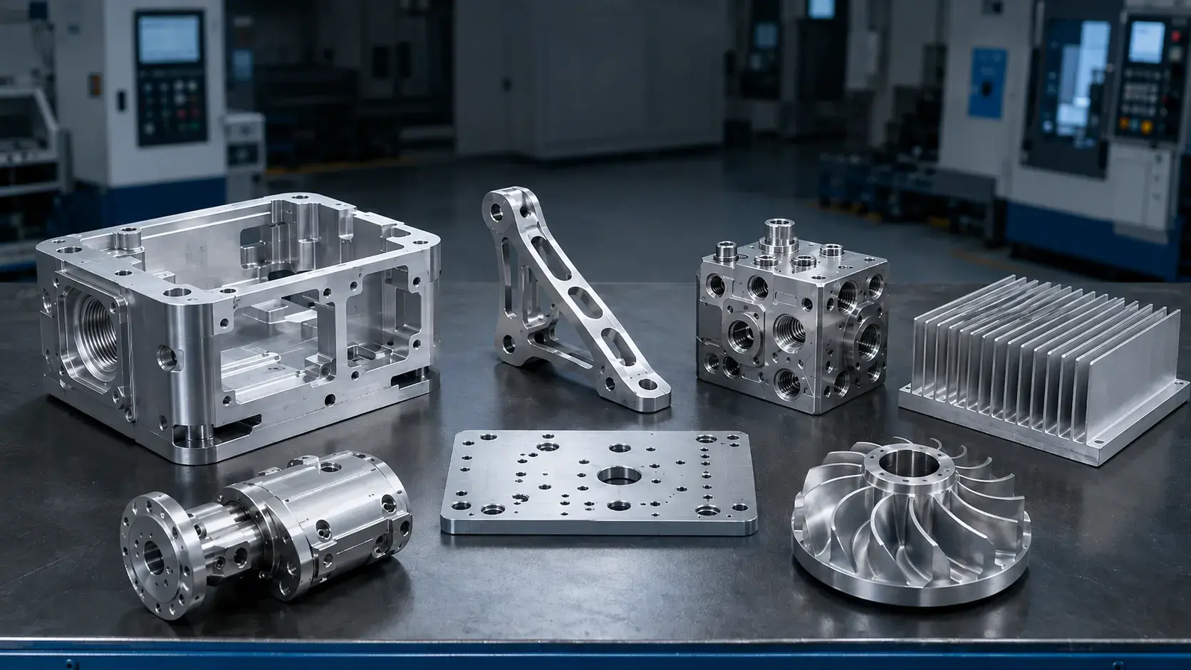
Different industries use CNC milling for different components, but several part types appear frequently in general manufacturing.
| Part Type | Common Features | Typical Materials |
|---|---|---|
| Housings and Enclosures | pockets, threads, sealing surfaces, bearing bores | 6061, 7075, stainless steel |
| Brackets and Mounts | ribs, holes, angled faces, weight-reduction pockets | aluminum, steel, titanium |
| Plates and Fixtures | hole patterns, dowel holes, locating surfaces | aluminum, tool steel |
| Manifolds | cross holes, ports, threads, sealing faces | aluminum, steel, stainless steel |
| Heat Sinks | fins, flat mounting surfaces, channels | aluminum |
| Mold and Tooling Parts | cavities, small radii, precision surfaces | tool steel, aluminum |
| Complex 3D Parts | curved surfaces, multi-side features, angled geometry | aluminum, titanium, steel |
Housings, Brackets, and Structural Parts
Housings and brackets are among the most common CNC milling parts.
Housings often contain internal pockets, threaded holes, sealing faces, bearing bores, and thin walls. Brackets may include ribs, mounting holes, angled surfaces, and lightweight pockets.
The main machining challenges usually involve wall deformation, deep cavities, flatness, and maintaining accurate relationships between multiple features.
Plates, Fixtures, and Manifolds
Plates and fixtures may appear simple, but they often require accurate hole position, flatness, and locating features.
Hydraulic and pneumatic manifolds are more complex because they contain intersecting holes, threaded ports, sealing surfaces, and internal passages.
For manifolds, burr removal and internal cleanliness can be as important as dimensional accuracy.
Heat Sinks, Tooling, and Complex 3D Parts
Heat sinks typically use aluminum because of its thermal conductivity and good machinability, but thin fins can vibrate or bend during cutting.
Mold inserts and tooling components often require fine finishes, deep cavities, or small internal radii.
Complex aerospace, robotic, medical, and turbine parts may require 3+2 or 5 axis machining when important surfaces cannot be reached efficiently from simple machining directions.
Common Features on CNC Milling Parts
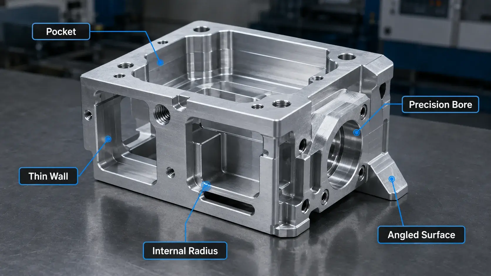
Most CNC milling parts are built from a combination of common machined features.
| Feature | Main Machining Consideration |
|---|---|
| Pockets | Deep pockets require longer and less rigid tools |
| Slots | Narrow or deep slots may require small cutters |
| Holes | Precision holes may need boring or reaming |
| Threads | Deep blind threads increase chip-removal difficulty |
| Thin Walls | Can flex or deform under cutting forces |
| Internal Corners | Small radii require smaller cutters |
| Undercuts | May require special tools or extra setups |
| Precision Bores | Diameter, position, and surface finish need tighter control |
| Complex 3D Surfaces | Require more finishing passes and longer machining time |
A part does not have to look complicated to be difficult to manufacture.
For example, a simple plate with several tightly positioned dowel holes may require more process control than a visually complex housing with relatively loose tolerances.
Machining difficulty depends more on geometry, tolerance, material, and tool access than appearance alone.CNC Milling Part Design Guidelines
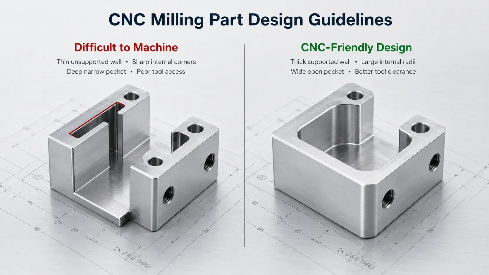
Good design can reduce machining time, improve dimensional stability, simplify workholding, and lower part cost.
The goal is not to remove every complex feature, but to avoid unnecessary difficulty where it does not improve the function of the part.
Keep Walls and Small Features Machinable
Thin walls can flex under cutting forces, causing dimensional variation, chatter, or distortion.
Very small holes, slots, pockets, and radii also require smaller tools, which are less rigid and remove material more slowly.
Where possible, avoid extremely thin unsupported walls and unnecessarily small features.
If thin geometry is functionally required, reduce unsupported height and provide enough surrounding material to improve rigidity.
Use Larger Internal Corner Radii
Rotating end mills cannot produce perfectly sharp internal corners.
Smaller corner radii require smaller cutters, which generally reduce rigidity and increase machining time.
Where possible, use an internal radius slightly larger than the cutter radius so the tool can move smoothly through the corner.
This is especially important in deep pockets.
Avoid Deep and Narrow Cavities
Deep cavities usually require long-reach tools.
As tool length increases, rigidity decreases, making vibration, deflection, and poor surface finish more likely.
If possible, reduce pocket depth, increase pocket width, or use larger internal radii so a larger cutter can reach the feature.
Deep cavities are possible, but they generally increase machining time.
Provide Good Tool Access
A feature may look easy in CAD but still be difficult to machine if nearby walls block the tool holder or spindle.
The complete tool assembly must be able to reach the cutting area without interference.
Undercuts should also be avoided unless they are functionally necessary, because they may require T-slot cutters, lollipop cutters, special tooling, or an additional machining direction.
Use Tight Tolerances Only Where Needed
Tight tolerances increase finishing and inspection requirements.
They may require slower cutting, additional measurements, tool compensation, and tighter process control.
Critical features such as bearing bores, locating holes, sealing surfaces, and mating interfaces may require tight tolerances, but non-functional dimensions usually do not.
Applying realistic tolerances only where needed is one of the simplest ways to reduce CNC milling cost.
Reduce Setups Through Better Feature Orientation
Every additional setup requires workholding, alignment, and machine time.
Repeatedly removing and repositioning a part can also affect positional accuracy between features machined in different orientations.
Where possible, group related features so they can be machined from common directions.
For more complex components, 4-axis, 3+2, or 5-axis machining may reduce the number of setups and improve accuracy between multi-side features.
Which CNC Milling Process Does Your Part Need?
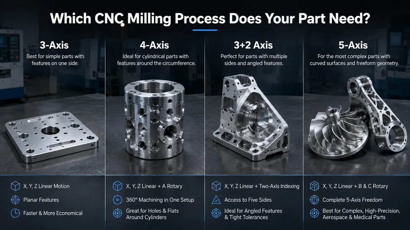
The right machining method depends mainly on part geometry and feature orientation.
A more advanced machine is not always necessary. Simple parts are often more economical on 3-axis equipment, while complex multi-side components may benefit from 4-axis or 5-axis machining.
| Part Geometry | Recommended Process |
|---|---|
| Flat plates and simple brackets | 3-axis |
| Parts with features around several sides | 4-axis |
| Components with angled faces | 3+2 axis |
| Multi-side structural parts | 3+2 or 5-axis |
| Complex curved surfaces | 5-axis |
| Impellers and turbine components | 5-axis |
3-axis machining is usually suitable when most features can be reached from one direction or with a few simple setups.
4-axis machining is useful for parts with features distributed around cylindrical or multi-side geometry.
3+2 machining is often used for angled surfaces that require different orientations but not simultaneous 5-axis movement.
Full 5-axis machining is most valuable when a part contains complex curved surfaces, difficult tool access, or features that need to remain accurately related across several orientations.
The main benefit of multi-axis machining is often fewer setups rather than simply having more machine axes.
Materials Used for CNC Milling Parts
CNC milling can be used with a wide range of metals and engineering plastics.
| Material | Common CNC Milling Parts | Main Reason for Use |
|---|---|---|
| Aluminum 6061 | housings, brackets, fixtures | good machinability and corrosion resistance |
| Aluminum 7075 | aerospace and structural parts | high strength-to-weight ratio |
| Stainless Steel | medical and industrial parts | corrosion resistance |
| Alloy Steel | fixtures and machine parts | strength and wear resistance |
| Titanium | aerospace and medical parts | high strength and low weight |
| Brass | fittings and electrical parts | machinability and conductivity |
| POM / Delrin | fixtures and mechanical components | dimensional stability |
| PEEK | medical and high-performance parts | temperature and chemical resistance |
Material selection should be based on part function rather than machinability alone.
Strength, weight, corrosion resistance, operating temperature, surface treatment, and cost should all be considered.What Affects the Cost of CNC Milling Parts?
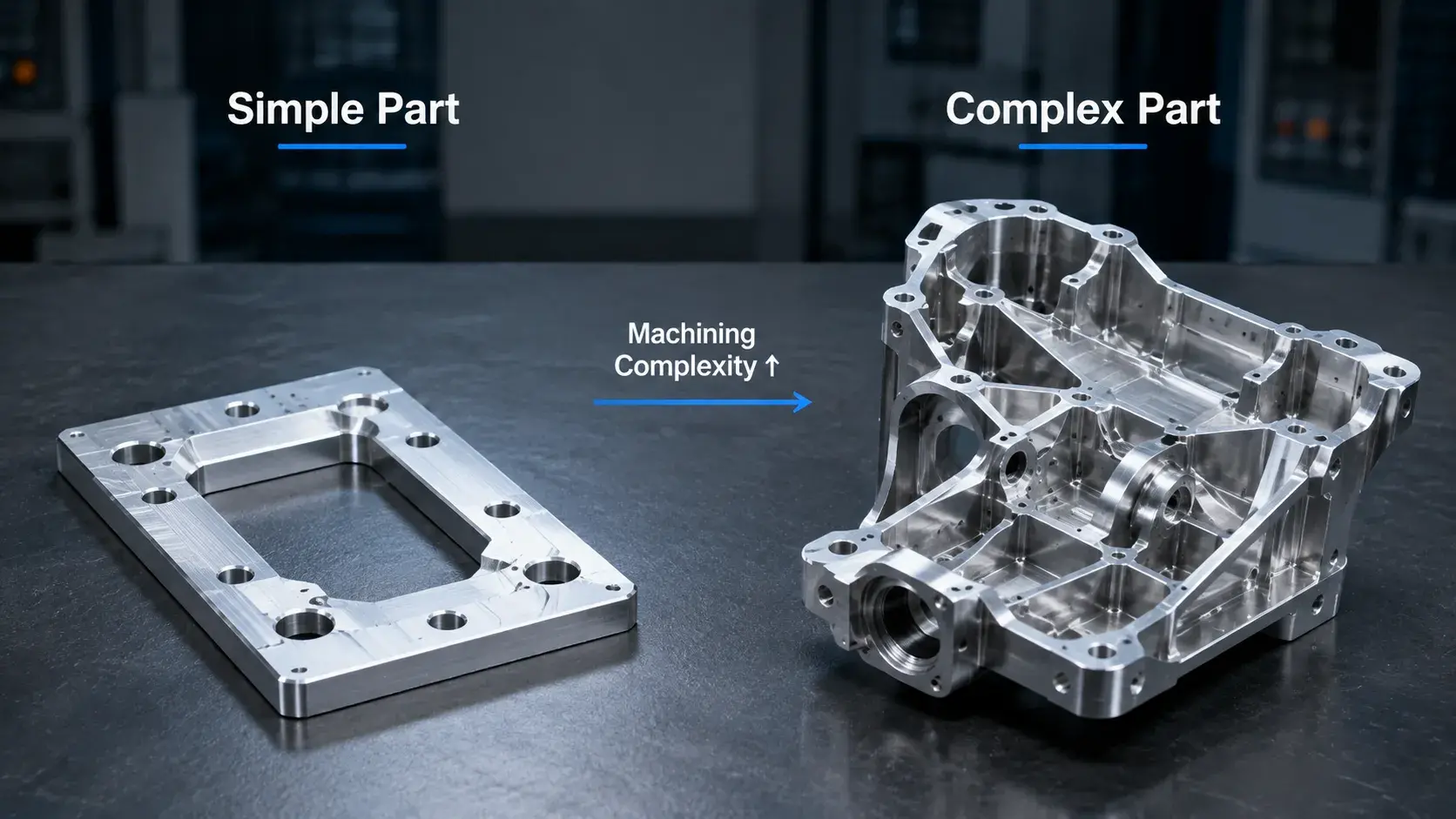
The cost of a CNC milling part depends on more than its overall size.
Two parts with similar dimensions can have very different prices if one contains deep pockets, tight tolerances, thin walls, or multiple machining orientations.
| Cost Factor | Why It Matters |
|---|---|
| Material | Affects raw stock cost and cutting speed |
| Geometry | Deep pockets and complex surfaces increase machining time |
| Setup Count | More setups require additional alignment and workholding |
| Tolerance | Tight tolerances require more finishing and inspection |
| Surface Finish | Polishing, anodizing, plating, and coating add processes |
| Quantity | Setup cost can be spread across more parts |
| Inspection | CMM, FAI, and detailed reports add inspection time |
A simple aluminum plate may require only a short machining cycle and one setup.
A thin-wall aerospace housing with deep pockets, angled features, and tight positional tolerances can require significantly more programming, machining, and inspection time.
For this reason, simplifying unnecessary features and tolerances can often reduce cost without affecting performance.
Need Custom CNC Milling Parts?
Send us your CAD files, drawings, material, quantity, and tolerance requirements. We can help review your design and manufacture precision CNC milling parts for prototypes and production.
Get a CNC Milling QuoteHow to Prepare a CNC Milling Part for Quotation
A complete RFQ helps the manufacturer evaluate the part correctly and identify possible machining issues before production.
For most CNC milling projects, provide:
- a 3D CAD file;
- a 2D drawing when tolerances or GD&T are important;
- material specification;
- quantity;
- required surface finish;
- critical tolerances;
- thread requirements;
- inspection requirements;
- target delivery date.
Common CAD formats include STEP, STP, IGES, and X_T.
The 3D model defines the geometry, while the 2D drawing can specify tolerances, threads, surface finish, GD&T, and other manufacturing requirements.
If only a few dimensions are critical, mark them clearly instead of applying tight tolerances to the entire part.
This allows the manufacturer to select a more suitable process and provide a more accurate quotation.
Conclusion
CNC milling parts range from simple plates and brackets to complex housings, manifolds, tooling components, and multi-axis aerospace parts.
The main factors that affect manufacturability are geometry, wall thickness, internal radii, tool access, tolerance, setup count, material, and inspection requirements.
Designing these features with machining in mind can reduce production time, improve consistency, and lower cost without changing the function of the part.
For custom CNC milling parts, providing a complete CAD model, drawing, material requirement, quantity, and critical tolerances is the best way to receive an accurate manufacturing evaluation and quotation.



