CNC machining works by converting a digital CAD design into programmed machine movements. CAM software creates toolpaths and G-code, which control how the cutting tool and machine axes move. The machine then removes material from a solid workpiece until the required shape, dimensions, and surface finish are achieved.
How Does CNC Machining Work?

CNC machining is a subtractive manufacturing process. Instead of building a part layer by layer, it starts with a solid block, plate, bar, or casting and removes unwanted material with cutting tools.
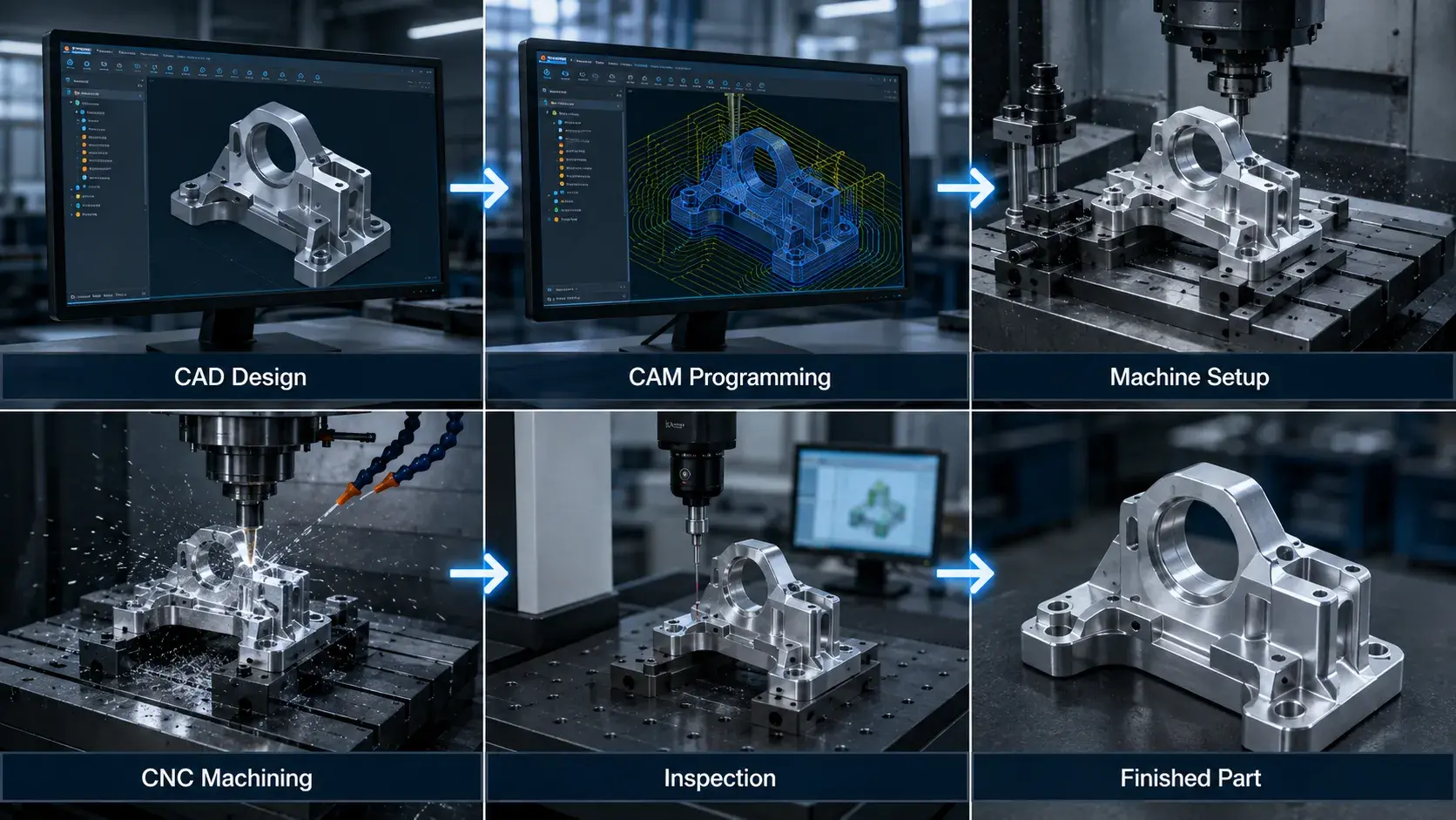
The basic CNC machining workflow is:
CAD Design → CAM Programming → Machine Setup → CNC Machining → Inspection → Finished Part
A CNC controller follows programmed instructions to control movements such as:
- X, Y, and Z axis travel;
- spindle speed;
- feed rate;
- cutting depth;
- tool changes;
- coolant flow;
- rotary axis movement on 4-axis and 5-axis machines.
The machine does not decide how to manufacture the part by itself. Engineers and machinists still need to choose the machining strategy, cutting tools, workholding method, cutting parameters, tolerances, and inspection requirements.
The CNC Machining Process Step by Step
Although the exact workflow varies by part, most CNC machining projects follow six main steps.
1. Create the CAD Design
The process begins with a digital model of the part.
A 3D CAD file defines the geometry, including features such as holes, pockets, bosses, slots, curves, and external profiles. Common file formats include:
- STEP or STP;
- IGES;
- Parasolid;
- SolidWorks files;
- DXF for 2D geometry.
For precision parts, a 2D engineering drawing is often provided together with the 3D model.
The drawing may specify requirements that are not fully defined by the CAD model, such as:
- dimensional tolerances;
- hole and thread specifications;
- surface roughness;
- geometric tolerances;
- material requirements;
- surface treatments;
- inspection notes.
In simple terms, the 3D CAD model defines the shape, while the engineering drawing defines how accurately and under what conditions the part must be manufactured.
2. Convert the CAD Model Into CAM Toolpaths
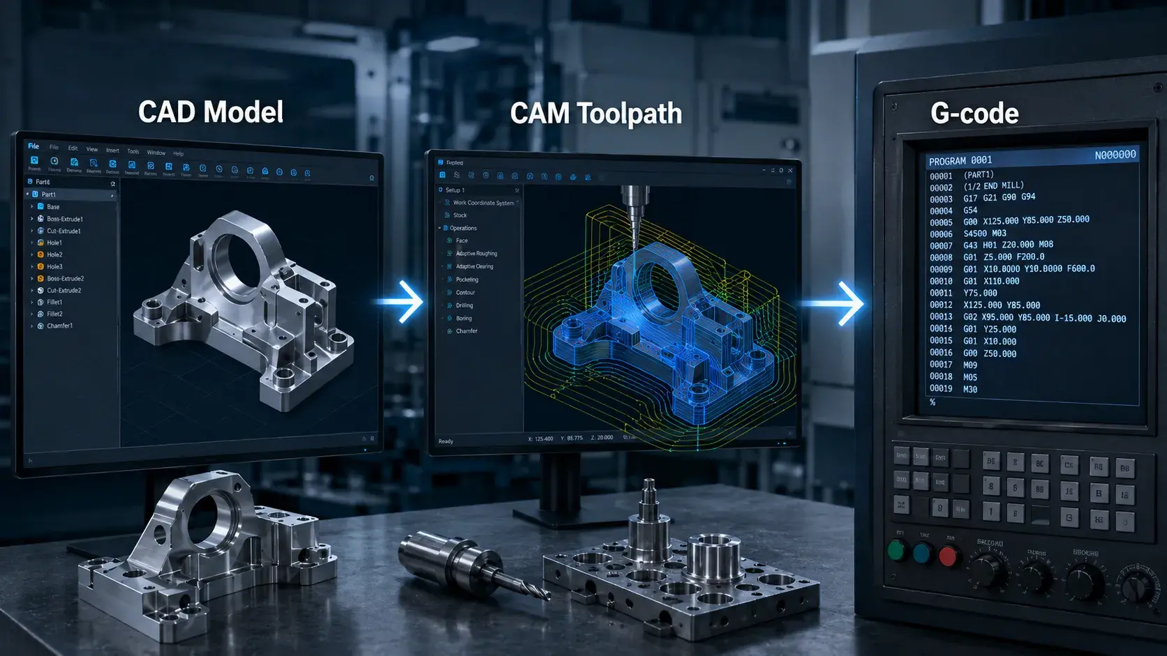
The CAD model is then imported into CAM software.
CAM software is used to define how cutting tools will remove material from the workpiece. The programmer selects machining operations, tools, cutting directions, feeds, speeds, and depths of cut.
Typical CAM decisions include:
- which tool machines each feature;
- the order of machining operations;
- spindle speed;
- feed rate;
- depth of cut;
- entry and exit movements;
- roughing and finishing strategies;
- tool changes.
The CAM system calculates the toolpaths and then uses a post-processor to convert them into machine-readable instructions.
These instructions are usually called G-code.
G-code primarily controls machine movement and positioning, while M-codes are commonly used for auxiliary functions such as spindle control, coolant, tool changes, and program stops.
The exact code depends on the CNC machine and controller being used.
3. Prepare the CNC Machine
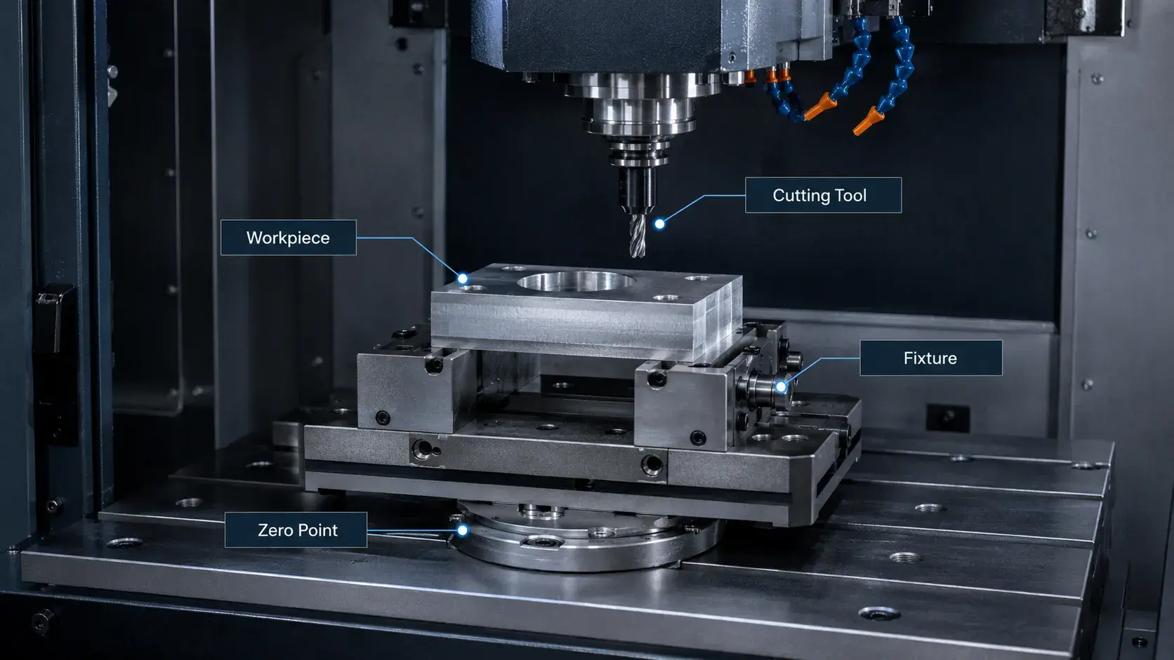
Before cutting begins, the CNC machine must be set up correctly.
The raw material is loaded and secured using a vise, chuck, fixture, soft jaws, clamps, or another workholding method.
Cutting tools are then installed in the machine’s tool holders or turret.
The machinist also needs to establish important reference values, including:
- workpiece zero point;
- tool length offsets;
- tool diameter offsets;
- fixture position;
- work coordinate system.
For production work, the first program is usually checked carefully before running at full speed.
This may involve simulation, a dry run, single-block operation, reduced feed rates, or machining a first article.
A correct setup is critical because even a good CNC program can produce an inaccurate part if the workpiece is positioned incorrectly or the tool offsets are wrong.
4. Run the Machining Operation
Once the program and setup are verified, machining begins.
The CNC controller reads the program and moves the machine axes according to the programmed toolpaths. Cutting tools remove material until each required feature is produced.
Different CNC machines create parts in different ways.
| CNC Process | How It Works | Typical Parts |
|---|---|---|
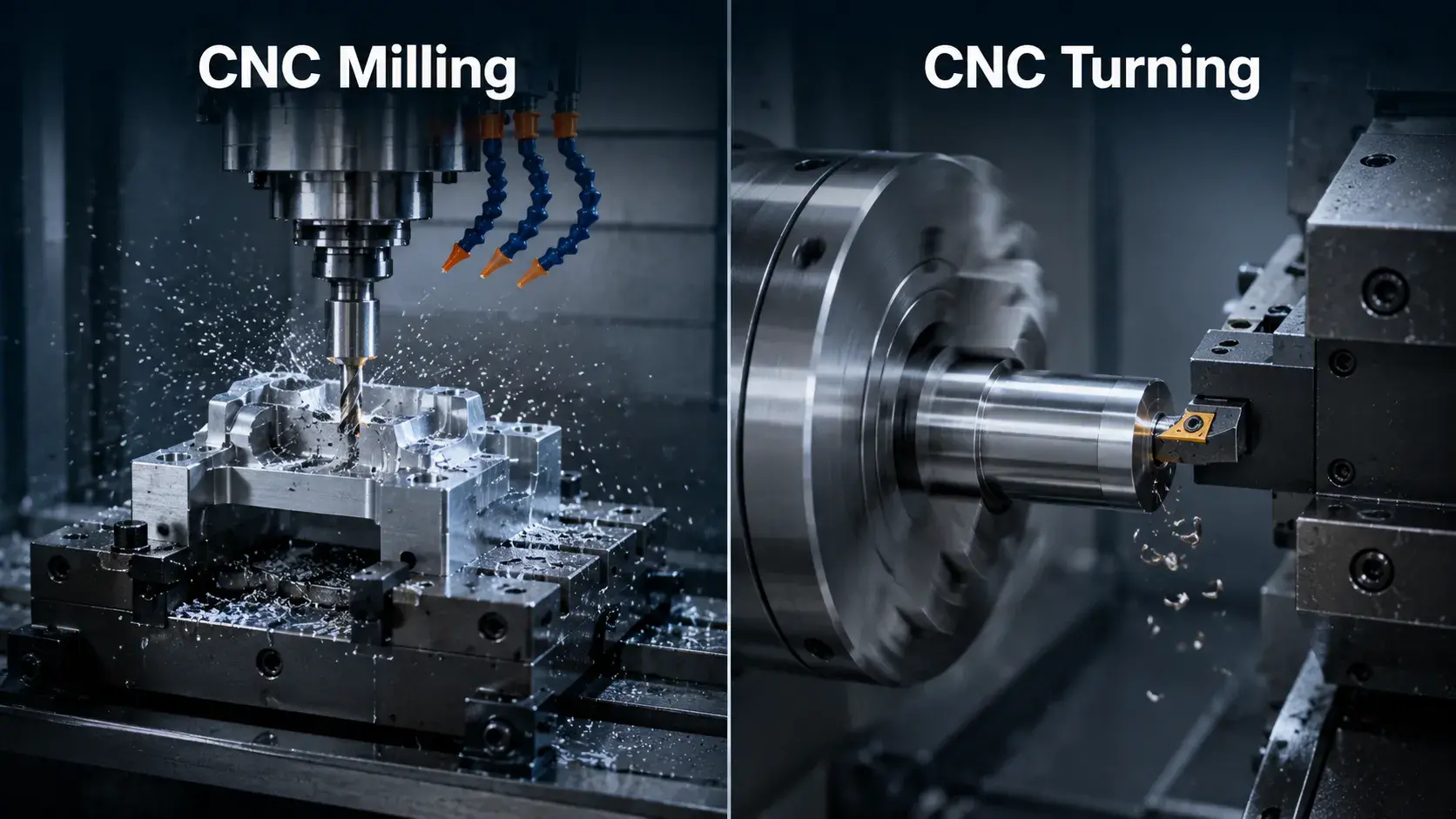
| CNC Milling | A rotating cutting tool removes material from a fixed or moving workpiece | Housings, brackets, pockets, plates, complex profiles |
| CNC Turning | The workpiece rotates while a cutting tool removes material | Shafts, pins, bushings, sleeves |
| Mill-Turn Machining | Turning and milling operations are combined in one machine | Complex rotational parts with holes, flats, and milled features |
| 5-Axis Machining | The cutting tool approaches the part from multiple angles | Aerospace parts, impellers, medical parts, complex surfaces |
CNC milling and turning are the two most common processes.
In CNC milling, the cutting tool rotates.
In CNC turning, the workpiece rotates.
More complex parts may require several machining operations, multiple setups, or a multi-axis machining center.
How Does a CNC Machine Know Where to Cut?
A CNC machine follows coordinates created from the original CAD model.
The process can be simplified as:
CAD Geometry → CAM Toolpath → G-code → CNC Controller → Machine Movement
The CNC controller reads coordinate commands and sends them to servo motors that move the machine axes.
On a standard 3-axis machine, these movements occur along the X, Y, and Z axes. A 4-axis or 5-axis machine adds rotary motion so the tool can reach the part from more directions.
Feedback systems monitor axis position and help keep the machine aligned with the programmed path.
What Happens During CNC Cutting?

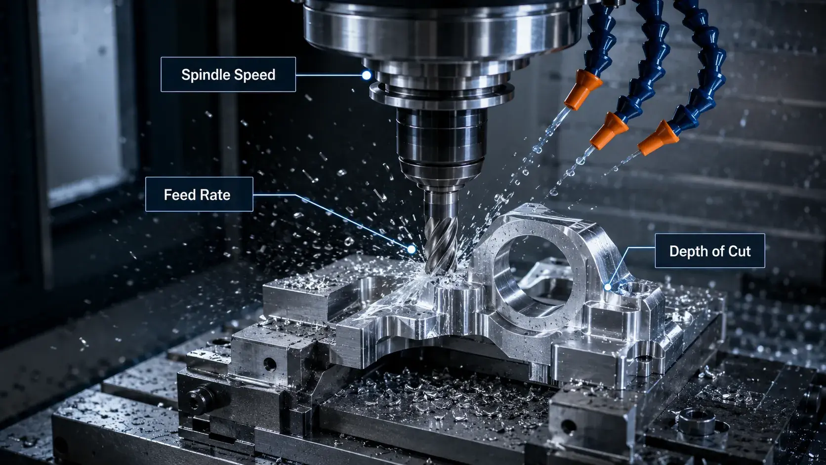
Three main parameters control how material is removed:
- Spindle speed: how fast the tool or workpiece rotates.
- Feed rate: how fast the cutting tool moves through the material.
- Depth of cut: how much material is removed in each pass.
These settings must match the cutting tool and material.
Incorrect cutting parameters can cause chatter, overheating, poor surface finish, excessive tool wear, or tool failure.
What Happens After CNC Machining?
Machining is often only one part of the manufacturing process.
After the main cutting operations are completed, the part may still require deburring, cleaning, surface finishing, heat treatment, or inspection before it is ready for use.
5. Deburring and Surface Finishing
Freshly machined parts may have sharp edges, small burrs, tool marks, or residues from coolant and cutting fluids.
Deburring removes these unwanted edges and improves handling, assembly, and appearance.
Depending on the application, CNC parts may also receive additional surface treatments such as:
- anodizing;
- passivation;
- powder coating;
- electroplating;
- polishing;
- bead blasting;
- black oxide;
- heat treatment.
Not every part requires secondary finishing.
For many internal mechanical components, the as-machined surface is already suitable for use. Cosmetic parts, corrosion-resistant components, or wear-resistant parts are more likely to need an additional finishing process.
6. Inspect the Finished Part
Inspection verifies whether the finished part matches the engineering drawing.
Typical checks may include:
- overall dimensions;
- hole diameter and position;
- thread size;
- flatness;
- perpendicularity;
- concentricity;
- surface roughness;
- geometric tolerances.
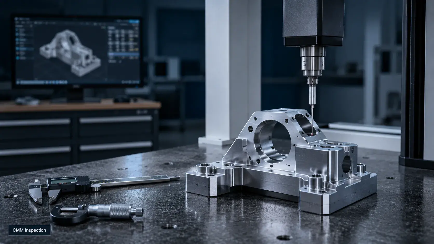
Simple dimensions can be checked with calipers, micrometers, gauges, or height gauges.
More complex parts may require a vision measuring machine, CMM, optical comparator, or other precision inspection equipment.
It is important to understand that CNC accuracy is not created by the machine alone.
Final part quality depends on the combination of machine capability, tooling, programming, fixturing, cutting conditions, operator control, and inspection.
CNC Milling vs CNC Turning: How Are They Different?

The easiest way to understand the difference is to look at what rotates.
In CNC milling, the cutting tool rotates while the workpiece is held in a fixture or moves along the machine axes.
In CNC turning, the workpiece rotates while a stationary or driven cutting tool removes material.
CNC milling is generally better suited to:
- pockets;
- flat surfaces;
- slots;
- complex profiles;
- housings;
- brackets.
CNC turning is generally better suited to:
- shafts;
- pins;
- sleeves;
- bushings;
- threaded cylindrical parts.
Many modern parts use both processes.
A mill-turn machine can complete turning, drilling, milling, tapping, and other operations in a single setup, reducing repositioning between machines.
How Accurate Is CNC Machining?

CNC machining can achieve high dimensional accuracy, but the required tolerance depends on the part geometry, material, machine, tooling, and inspection method.
General CNC machining commonly works within about ±0.025 mm to ±0.1 mm, while precision machining may achieve around ±0.005 mm to ±0.01 mm on suitable features.
Tighter tolerances usually increase machining and inspection cost, so they are best applied only to critical dimensions.
What Materials Can CNC Machines Cut?
CNC machining works with a wide range of metals and engineering plastics.
Common materials include:
| Material Group | Common Grades |
|---|---|
| Aluminum | 6061, 7075, 2024, 5052 |
| Stainless Steel | 303, 304, 316, 17-4PH |
| Carbon and Alloy Steel | Mild steel, 4140, tool steel |
| Titanium | Grade 2, Grade 5 |
| Copper Alloys | Brass, copper, bronze |
| Engineering Plastics | POM, PEEK, Nylon, ABS, PC, PTFE |
Different materials require different cutting speeds, tools, coolant strategies, and machining methods.
Aluminum is generally easier and faster to machine than titanium or hardened steel, while some plastics require careful control to avoid melting, warping, or poor surface finish.
Material selection therefore affects both part performance and machining cost.
How Much Does CNC Machining Cost?
CNC machining cost is mainly determined by how much manufacturing time and effort the part requires.
The main cost factors include:
- material;
- machine time;
- programming;
- setup;
- cutting tools;
- number of setups;
- part complexity;
- tolerances;
- surface finishing;
- inspection requirements;
- order quantity.
Machine time is often one of the largest cost drivers.
A complex 5-axis part that requires several hours of machining will normally cost much more than a simple turned spacer that can be completed in minutes.
Quantity also matters.
Programming and setup costs are spread across more parts as production volume increases, so the cost per part often decreases at higher quantities.
How to Prepare a Part for CNC Machining
A clear RFQ package helps a machine shop understand exactly what needs to be manufactured.
For most CNC projects, it is useful to provide:
- 3D CAD file
STEP or another common solid-model format is usually preferred. - 2D engineering drawing
Include critical tolerances, threads, surface finish, and inspection requirements. - Material specification
Specify both the material type and grade where necessary. - Quantity
Prototype, low-volume, and production quantities may use different machining strategies. - Surface finish requirements
State whether the part should remain as-machined or receive anodizing, plating, polishing, or another treatment. - Critical dimensions
Clearly identify which features require tight tolerances. - Inspection requirements
Specify whether dimensional reports, CMM inspection, material certificates, or other documentation are needed.
Complete information reduces quoting uncertainty and helps engineers choose a more efficient machining process.
From CAD File to Finished CNC Part
CNC machining may look highly automated, but producing a good part still requires engineering decisions at every stage.
The complete process can be summarized as:
CAD Design → CAM Programming → G-code → Machine Setup → Material Cutting → Finishing → Inspection → Finished Part
The CNC controller provides accurate and repeatable machine movement, while engineers and machinists determine how the part should be held, cut, measured, and finished.
For simple parts, the process may involve only a few operations.
For complex precision components, it may require multiple tools, several machining strategies, multi-axis motion, secondary finishing, and detailed inspection before the part is complete.
Need CNC Machined Parts?
Send us your CAD files, drawings, material, and quantity. We can help you review the design, confirm the machining process, and provide a fast quote.