

Surface roughness describes the small irregularities left on a surface after machining or finishing. The most common parameter is Ra, usually expressed in µm or µin.
In general, a lower Ra value means a smoother surface. For example, Ra 0.8 µm is smoother than Ra 3.2 µm.
The chart below gives a quick reference for common surface roughness values used in machining.
Surface Roughness Chart
| Ra (µm) | Ra (µin) | N Grade | Typical Description |
|---|---|---|---|
| 25 | 1000 | N11 | Very rough machined surface |
| 12.5 | 500 | N10 | Rough machining |
| 6.3 | 250 | N9 | Coarse machined finish |
| 3.2 | 125 | N8 | Standard machined finish |
| 1.6 | 63 | N7 | Good machined finish |
| 0.8 | 32 | N6 | Fine machined finish |
| 0.4 | 16 | N5 | Precision finish |
| 0.2 | 8 | N4 | Very fine finish |
| 0.1 | 4 | N3 | Fine lapped or polished finish |
| 0.05 | 2 | N2 | Very smooth precision finish |
| 0.025 | 1 | N1 | Extremely fine finish |
The values above are useful as a general engineering reference. Actual achievable roughness depends on the machining process, material, tool condition, cutting parameters, machine rigidity, and finishing method.
A common CNC-machined surface may fall around Ra 1.6 to 3.2 µm, while grinding, honing, lapping, or polishing may be needed for much smoother finishes.
What Is Surface Roughness?
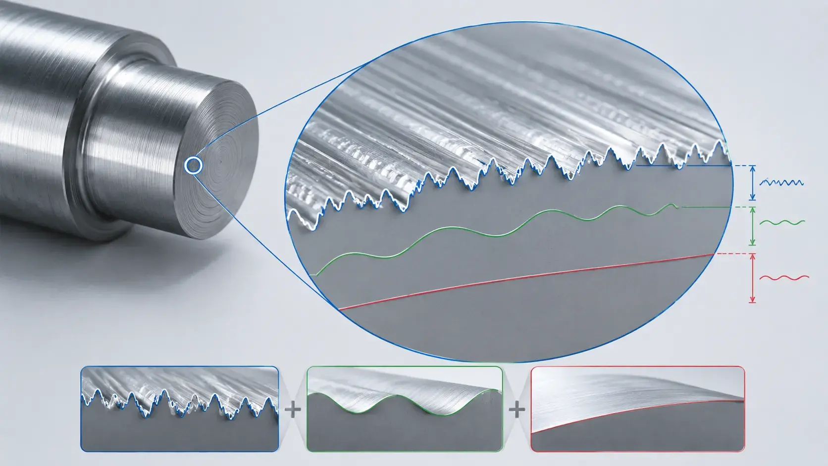
Surface roughness is the fine, closely spaced variation in the height of a surface.
Even a machined metal part that looks smooth to the eye contains microscopic peaks and valleys. Surface roughness measurements describe the size and distribution of these irregularities.
Surface texture is usually divided into three main elements:
- Roughness: small, closely spaced surface irregularities
- Waviness: larger and more widely spaced surface variation
- Lay: the main direction of the surface pattern
Roughness is usually the parameter most commonly specified on CNC machining drawings.
A turned surface, for example, may show circular tool marks, while a milled surface may show directional cutter marks. These patterns affect friction, sealing, wear, coating, appearance, and part performance.
What Does Ra Mean?
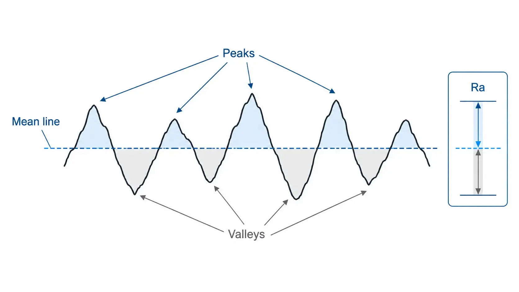
Ra means arithmetic average roughness.
It is the most commonly used surface roughness parameter in manufacturing.
Ra represents the average deviation of the measured surface profile from the mean line over a specified sampling length.
In simple terms:
Ra tells you the average height of the small peaks and valleys on a surface.
A lower Ra number generally indicates a smoother surface.
For example:
- Ra 6.3 µm = relatively rough machined surface
- Ra 3.2 µm = common machined surface
- Ra 1.6 µm = smoother precision-machined surface
- Ra 0.8 µm = fine finish
- Ra 0.4 µm = very smooth precision finish
Ra is popular because it provides a simple numerical value that is easy to specify, measure, and compare.
However, two surfaces can have the same Ra value while having different peak shapes, valley depths, or surface patterns. This is why other roughness parameters such as Rz may also be important.
What Do Rz, Rq, and Rt Mean?
Ra is not the only surface roughness parameter.
Different parameters describe different characteristics of the measured surface profile.
| Parameter | Meaning | What It Describes |
|---|---|---|
| Ra | Arithmetic average roughness | Average surface deviation |
| Rz | Average maximum profile height | Larger peak-to-valley variation |
| Rq | Root mean square roughness | Statistical average weighted toward larger deviations |
| Rt | Total profile height | Highest peak to deepest valley over the evaluation length |
Ra vs Rz
Ra and Rz are often used together, but they measure the surface differently.
Ra gives an average value, while Rz is more sensitive to larger peaks and deeper valleys.
This means a surface with an acceptable Ra value may still contain an unusually deep scratch or surface defect that becomes more visible in an Rz measurement.
For general CNC machining drawings, Ra is usually sufficient.
Rz may be more useful when deep valleys, sealing performance, fatigue, lubrication, or surface defects are especially important.
There is no single fixed conversion factor between Ra and Rz because the relationship depends on the actual surface profile.
Surface Roughness Symbols Explained
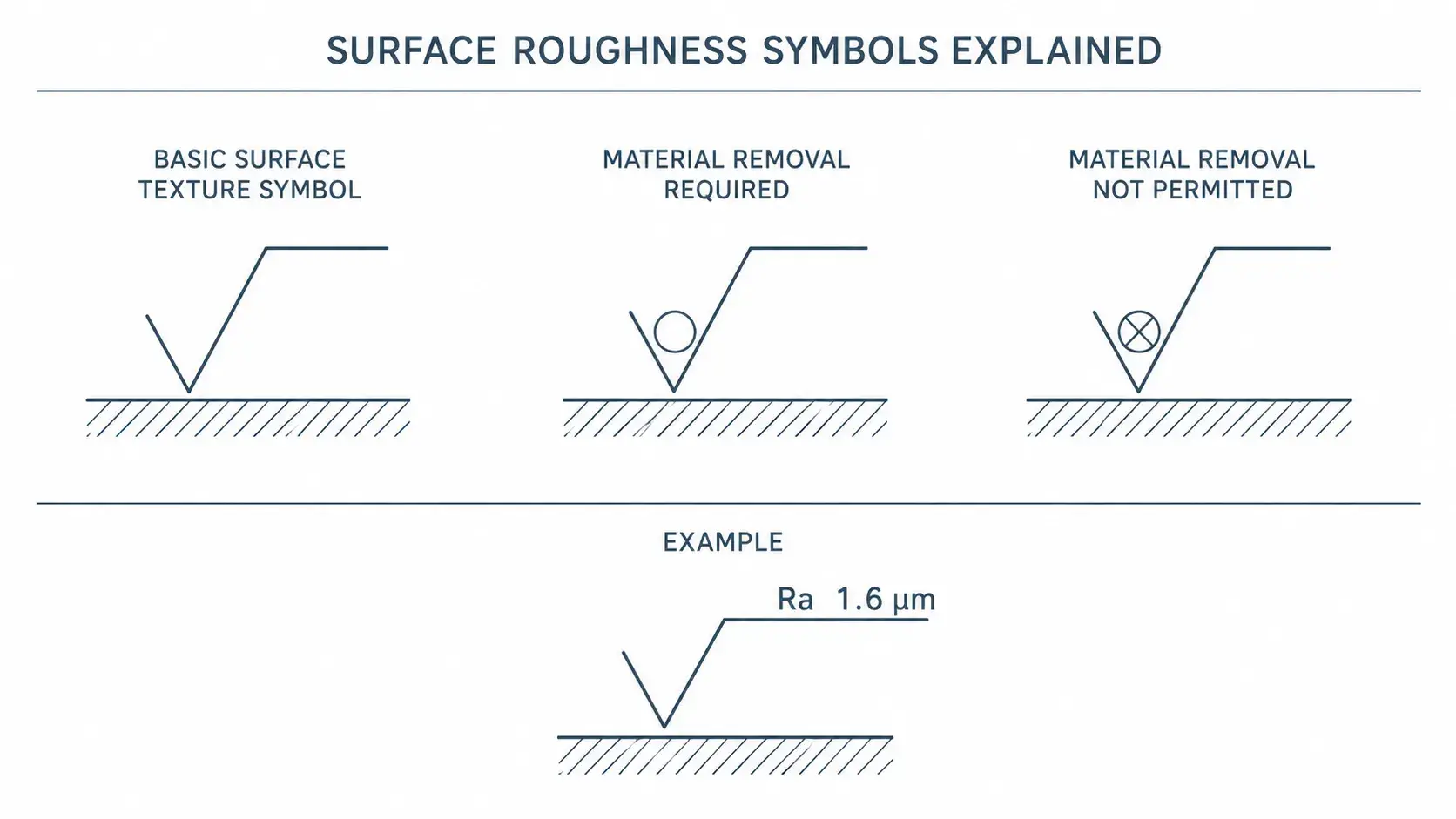
Engineering drawings use standardized surface texture symbols to tell manufacturers what surface condition is required.
A basic surface texture symbol looks similar to a check mark.
Additional lines, values, and notes can then be added to specify machining and surface requirements.
The three most common symbol forms are:
| Symbol Type | Meaning |
|---|---|
| Basic surface texture symbol | A surface texture requirement applies |
| Symbol with horizontal bar | Material removal is required |
| Symbol with circle | Material removal is not permitted |
A drawing may also include:
- Ra or Rz value
- Maximum or minimum roughness
- Machining allowance
- Sampling length
- Surface lay direction
- Required production method
For example, a drawing marked with:
Ra 1.6 µm
means the specified surface should meet a roughness value of approximately Ra 1.6 µm or smoother, depending on the drawing requirement.
Surface roughness symbols should always be interpreted together with the drawing standard being used.Surface Roughness Conversion Chart
Surface roughness may be specified in micrometers or microinches.
The basic conversion is:
1 µm = 39.37 µin
The table below shows common approximate conversions.
| Ra (µm) | Ra (µin) |
|---|---|
| 25 | 1000 |
| 12.5 | 500 |
| 6.3 | 250 |
| 3.2 | 125 |
| 1.6 | 63 |
| 0.8 | 32 |
| 0.4 | 16 |
| 0.2 | 8 |
| 0.1 | 4 |
| 0.05 | 2 |
| 0.025 | 1 |
In U.S. engineering drawings, values such as 32 µin, 63 µin, 125 µin, and 250 µin are commonly used.
These correspond approximately to:
- 32 µin = Ra 0.8 µm
- 63 µin = Ra 1.6 µm
- 125 µin = Ra 3.2 µm
- 250 µin = Ra 6.3 µm
Typical Surface Roughness by Machining Process
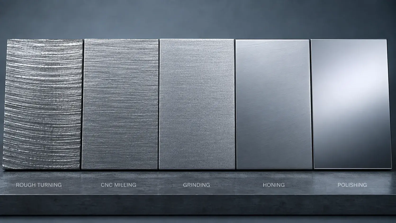
Different manufacturing processes naturally produce different surface roughness ranges.
The table below gives typical values.
| Process | Typical Ra Range |
|---|---|
| Sawing | 6.3–25 µm |
| Rough Turning | 3.2–12.5 µm |
| CNC Milling | 1.6–6.3 µm |
| Fine Turning | 0.8–3.2 µm |
| Precision Milling | 0.8–3.2 µm |
| Reaming | 0.4–1.6 µm |
| Grinding | 0.2–1.6 µm |
| Honing | 0.1–0.8 µm |
| Lapping | 0.025–0.4 µm |
| Polishing | 0.025–0.8 µm |
These ranges are only typical values.
Actual results depend on factors such as:
- Material
- Cutting tool geometry
- Tool wear
- Cutting speed
- Feed rate
- Depth of cut
- Machine condition
- Coolant
- Part rigidity
- Toolpath strategy
For CNC machining, feed rate and tool geometry have a particularly strong influence on the final surface pattern.
What Surface Roughness Should You Specify?
The correct surface roughness depends on the function of the part.
A smoother surface is not always better.
Over-specifying surface finish can increase machining time, tool wear, inspection requirements, and manufacturing cost.
Ra 6.3 µm
Suitable for relatively rough or non-critical machined surfaces.
Typical uses include:
- Hidden surfaces
- Non-contact surfaces
- Rough-machined features
- General structural parts
Ra 3.2 µm
Ra 3.2 µm is a very common general machining requirement.
It is often suitable for:
- General CNC-machined surfaces
- Housings
- Brackets
- Non-critical mating surfaces
- Standard industrial components
Ra 1.6 µm
Ra 1.6 µm provides a smoother machined finish.
It may be used for:
- Precision mating surfaces
- Shafts
- Bores
- Sliding components
- Higher-quality visible surfaces
Ra 0.8 µm
Ra 0.8 µm is considered a fine finish for many machined parts.
Typical applications may include:
- Bearing fits
- Sealing surfaces
- Precision sliding surfaces
- High-quality functional surfaces
Depending on the geometry and material, this finish may require fine machining, grinding, honing, or another finishing operation.
Ra 0.4 µm and Below
Very smooth finishes are usually specified only when the function requires them.
Applications may include:
- Precision sealing surfaces
- Hydraulic components
- Bearing surfaces
- Medical parts
- Optical or high-precision components
Processes such as grinding, honing, lapping, or polishing may be required.
Is a Lower Ra Always Better?
No.
A lower Ra value produces a smoother surface, but smoother is not automatically better for every application.
Some surfaces require a certain amount of texture.
For example, surface texture may help:
- Retain lubricant
- Improve coating adhesion
- Control friction
- Support sealing behavior
Specifying an unnecessarily low Ra value can also increase manufacturing cost.
A surface that can be produced at Ra 3.2 µm directly from CNC machining may require slower cutting, additional passes, grinding, or polishing to reach Ra 0.4 µm.
The surface roughness requirement should therefore be based on the actual function of the component.
How Is Surface Roughness Measured?
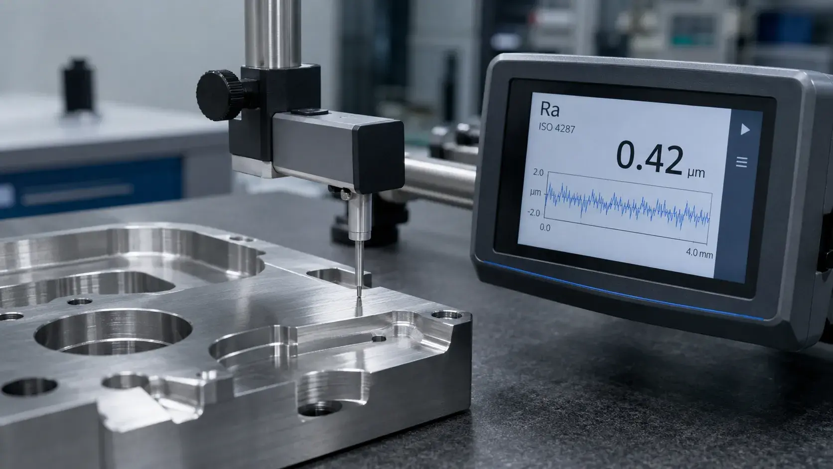
Surface roughness can be measured using contact or non-contact methods.
Stylus Profilometer
A stylus profilometer is one of the most common tools used for machined parts.
A small stylus moves across the surface and records the vertical changes in the surface profile.
The instrument then calculates values such as Ra or Rz.
Stylus instruments are widely used because they are practical, accurate, and suitable for many metal components.
Optical Profilometer
Optical systems measure surface texture without physically touching the part.
They may use light, interferometry, or other optical methods to create a detailed surface profile.
Optical measurement is useful for delicate surfaces, very fine finishes, and applications where contact measurement could damage the part.
Surface Roughness Comparator
A surface roughness comparator contains reference samples with known roughness levels.
The inspector compares the machined surface visually or by touch against the samples.
This method is quick and inexpensive, but it is less precise than direct instrument measurement.
For dimensional inspection and formal surface roughness verification, a calibrated roughness tester is usually preferred.
Why Does Surface Roughness Matter?
Surface roughness can directly affect how a component performs.
Important effects include:
- Friction: rougher surfaces may increase friction.
- Wear: surface peaks can affect sliding wear.
- Sealing: deep valleys may create leakage paths.
- Lubrication: surface texture can help retain oil.
- Fatigue: surface irregularities may act as stress concentration points.
- Coating: texture can influence coating adhesion.
- Appearance: smoother surfaces often look more uniform.
- Fit: roughness can influence contact between mating components.
This is why surface roughness should be treated as a functional engineering requirement rather than only a cosmetic specification.
Is Surface Roughness the Same as Surface Finish?
Not exactly.
Surface roughness is a measurable component of surface texture.
Surface finish is a broader term that may refer to the overall condition or appearance of a surface.
In everyday manufacturing language, machinists often use “surface finish” when referring specifically to Ra roughness.
However, technically, surface texture may include:
- Roughness
- Waviness
- Lay
- Surface defects
So, the terms are closely related but not completely identical.
Can CNC Machining Achieve Ra 0.8 µm?
Yes, in some cases.
A well-controlled CNC milling or turning process can achieve approximately Ra 0.8 µm, depending on:
- Material
- Tool geometry
- Cutting parameters
- Tool condition
- Machine rigidity
- Workholding
- Feature geometry
However, Ra 0.8 µm should not automatically be assumed for every CNC-machined surface.
For difficult materials, deep features, interrupted cuts, or very tight surface requirements, grinding, honing, or polishing may be more reliable.
What Ra Is Considered a Mirror Finish?
There is no single universal Ra value that defines a mirror finish because appearance also depends on material, polishing method, and light reflection.
However, mirror-like metal finishes are often associated with very low roughness values, typically around Ra 0.1 µm or below.
Highly polished surfaces may reach Ra values around 0.05 µm or lower.
A low Ra value alone does not always guarantee a visually perfect mirror finish, because scratches, waviness, and directional polishing marks can still affect appearance.
Conclusion
A surface roughness chart helps engineers compare common Ra values, surface finish grades, machining processes, and drawing requirements.
For most CNC machining applications:
- Ra 3.2 µm is a common general machined finish.
- Ra 1.6 µm is a smoother precision-machined finish.
- Ra 0.8 µm is used for finer functional surfaces.
- Ra 0.4 µm or below may require grinding, honing, lapping, or polishing.
The best surface roughness is not necessarily the lowest number.
It is the roughness level that provides the required function without adding unnecessary manufacturing cost.



