

A reliable snap fit depends on the right joint type, beam geometry, material, deflection, root radius, and clearance. For cantilever snap fits, controlling strain during assembly is one of the most important design considerations.
This guide explains the main snap fit types, key dimensions, basic calculations, practical design rules, material selection, tolerances, and common failure problems.
What Is a Snap Fit?
A snap fit is a mechanical fastening feature that joins two parts by allowing one feature to temporarily deform during assembly.
The flexible feature may bend, twist, expand, or compress as the parts are pushed together. Once it passes the mating feature, it returns toward its original shape and locks into place.
Snap fits are widely used in plastic housings, electronic enclosures, automotive parts, medical devices, covers, caps, and consumer products because they can reduce screws, adhesives, and other separate fasteners.
The main design challenge is simple: the snap feature must flex enough to assemble without exceeding the material’s allowable strain, while still providing enough retention after engagement.
Types of Snap Fits
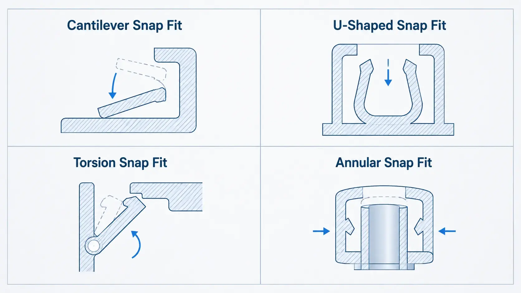
Most snap-fit designs fall into four common categories.
| Snap Fit Type | How It Works | Best Used For | Main Design Concern |
|---|---|---|---|
| Cantilever | Flexible beam bends during assembly | Housings, covers, clips | Root strain |
| U-shaped | Longer curved beam bends | Limited-space designs | Beam flexibility |
| Torsion | Feature twists around an axis | Releasable latches | Torsional stress |
| Annular | Circular feature expands or compresses | Caps, tubes, connectors | Interference |
Cantilever Snap Fit
The cantilever snap fit is the most common type.
It uses a beam fixed at one end with a hook or projection at the free end. During assembly, the beam bends until the hook passes the mating edge and snaps into place.
Because cantilever snap fits are so widely used, most snap-fit design rules and calculations focus on this type.
U-Shaped Snap Fit
A U-shaped snap fit folds the beam back toward the main body.
This increases the effective beam length and allows more deflection in a relatively compact area.
It is useful when a straight cantilever would otherwise be too short or too stiff.
Torsion Snap Fit
A torsion snap fit works by twisting rather than mainly bending.
These designs are commonly used in reusable latches and release mechanisms where controlled opening and closing are required.
Annular Snap Fit
Annular snap fits are used on round parts.
One circular feature expands or compresses as it passes a mating ridge or groove. They are common in caps, cylindrical housings, tubes, and connectors.Key Dimensions in a Cantilever Snap Fit
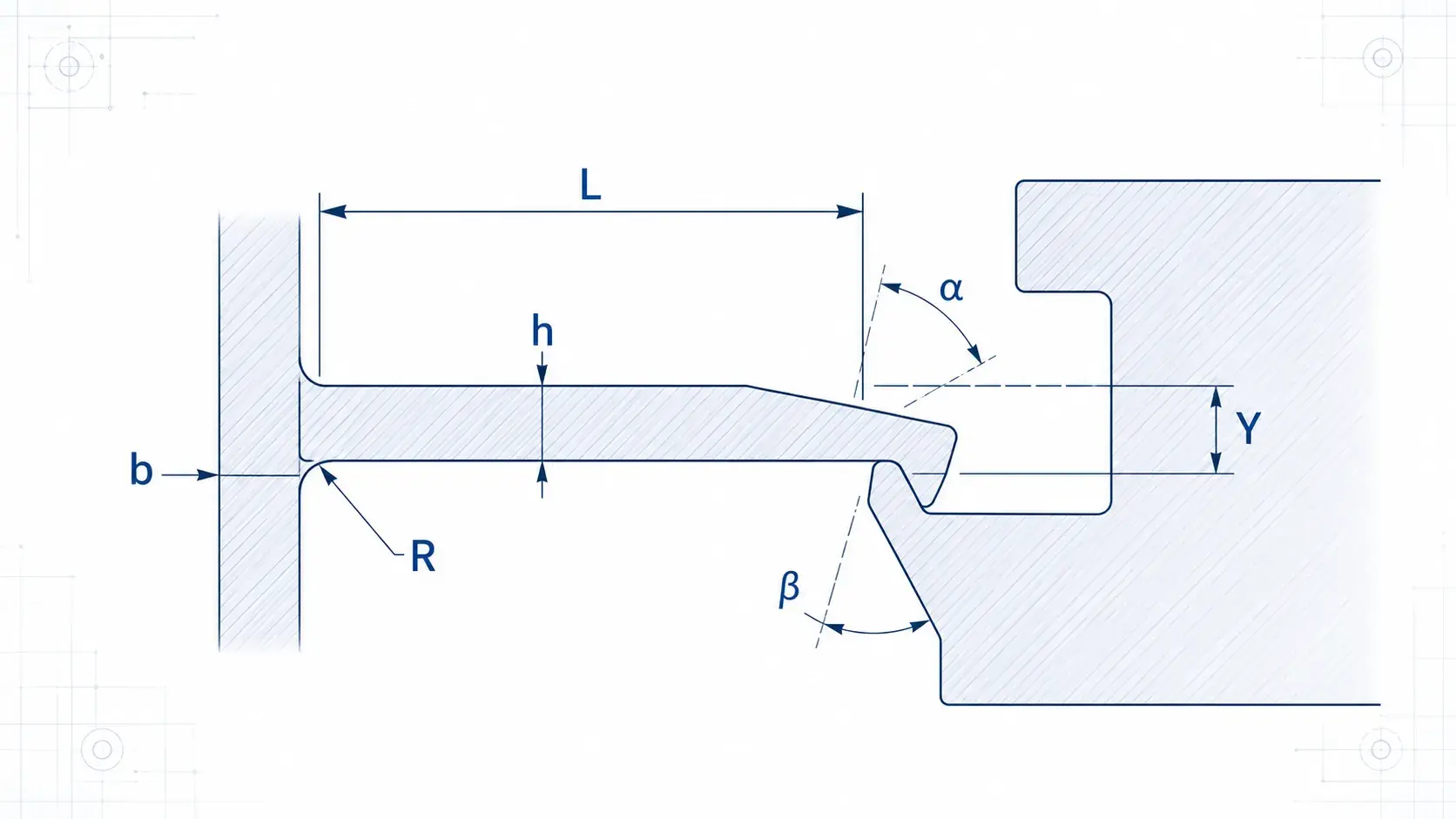
A cantilever snap fit is mainly controlled by a few key dimensions:
- L – Beam length
- h – Beam thickness
- b – Beam width
- Y – Required deflection
- R – Root radius
- α – Lead-in angle
- β – Retention angle
These dimensions directly affect strain, assembly force, and retention.
In general:
- A longer beam is more flexible.
- A thicker beam is stiffer.
- Greater deflection increases strain.
- A larger root radius reduces stress concentration.
- A smoother lead-in angle reduces assembly force.
- A steeper retention angle increases pull-out resistance.
These relationships are more useful during early design than relying on one fixed snap-fit size.
How Do You Calculate Snap Fit Strain?
For a simple rectangular cantilever beam, the maximum surface strain can be estimated using:
ε ≈ 1.5 × h × Y / L²
Where:
- ε = strain
- h = beam thickness
- Y = required tip deflection
- L = beam length
This simple relationship shows why beam geometry matters so much.
If beam length increases, strain drops significantly.
If beam thickness or required deflection increases, strain rises.
For example:
- Longer beam → lower strain
- Thicker beam → higher strain
- More deflection → higher strain
The calculated strain should remain below the allowable strain of the selected material with an appropriate safety margin.
This equation is useful for first-pass design, but real snap fits may also be affected by tapered geometry, friction, large deflection, stress concentration, temperature, and repeated loading.
Snap Fit Design Guidelines
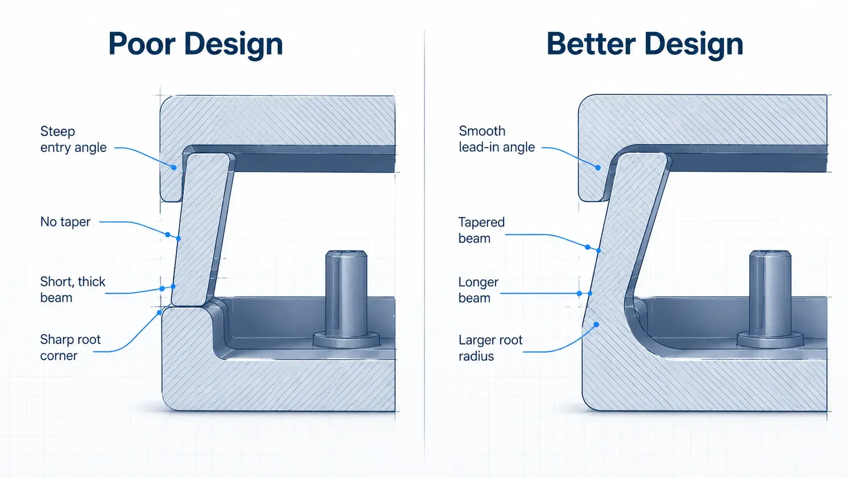
A few practical design rules can prevent most snap-fit problems.
| Design Parameter | Practical Guideline | Why It Matters |
|---|---|---|
| Beam length | Use enough length for required deflection | Reduces strain |
| Beam thickness | Avoid short, overly thick beams | Prevents excessive stiffness |
| Root radius | Add a generous fillet | Reduces stress concentration |
| Beam taper | Gradually reduce thickness toward the tip | Improves strain distribution |
| Lead-in angle | Use a smooth entry surface | Reduces assembly force |
| Retention angle | Match it to removable or permanent use | Controls pull-out force |
| Undercut | Use only as much as needed | Limits required deflection |
| Stops | Prevent excessive bending | Protects the beam |
| Clearance | Include manufacturing tolerance | Improves assembly consistency |
Use a Larger Root Radius
The highest stress in a cantilever snap fit normally occurs near the fixed end of the beam.
A sharp corner at this location can create a strong stress concentration.
As a practical starting point, a root radius of around:
R ≥ 0.5 × beam thickness
is commonly used.
This is not a universal rule, but it is a useful starting value for many plastic snap-fit designs.
Avoid Short, Thick Beams
A short and thick snap feature may look strong, but it is often too stiff.
This increases assembly force and local strain.
If more flexibility is needed, increasing beam length is usually more effective than simply making the beam thinner.
Use a Tapered Beam Where Possible
A constant-thickness beam often concentrates strain near the root.
A gradual taper toward the free end can distribute strain more evenly and reduce peak stress.
Control the Lead-In and Retention Angles
The lead-in angle determines how easily the mating part pushes the snap feature aside.
A smoother lead-in reduces assembly force.
The retention angle determines how strongly the joint resists removal.
A steeper retention angle may be appropriate for a permanent joint, while reusable snap fits need geometry that allows controlled release.
What Materials Are Best for Snap Fits?
The best material is not simply the strongest material.
Snap-fit materials need enough flexibility to deform and enough elastic recovery to return close to their original shape.
| Material | Snap Fit Characteristics |
|---|---|
| PP | Excellent flexibility and fatigue resistance |
| Nylon / PA | Tough and suitable for repeated loading |
| POM | Low friction and good dimensional stability |
| PC | Strong with good impact resistance |
| ABS | Common and easy to prototype |
| PEEK | High strength and temperature resistance |
Important properties include:
- Allowable strain
- Elastic recovery
- Fatigue resistance
- Creep resistance
- Temperature resistance
- Moisture sensitivity
Filled plastics also require special attention.
For example, glass-filled materials may provide higher stiffness but lower elongation, which can make snap features more sensitive to cracking.
How Much Clearance Should a Snap Fit Have?
There is no universal snap-fit clearance.
The correct clearance depends on:
- Material
- Part size
- Manufacturing process
- Required retention
- Surface finish
- Assembly direction
- Dimensional tolerance
Some small plastic assemblies may use clearances around 0.1–0.5 mm as a rough prototyping reference, but this should not be treated as a fixed design rule.
A fit that is too tight can cause:
- High assembly force
- Excessive beam strain
- Cracking
A fit that is too loose can cause:
- Rattle
- Poor retention
- Misalignment
Tolerance stack-up should also be considered because both mating parts may vary within specification.
Why Do Snap Fits Fail?
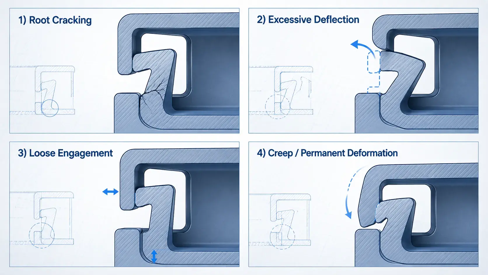
Most snap-fit failures come from a small number of design problems.
| Problem | Likely Cause | Possible Fix |
|---|---|---|
| Snap breaks during assembly | Excessive strain or sharp root | Increase beam length or root radius |
| Assembly force is too high | Beam too stiff or lead-in too steep | Reduce stiffness or entry angle |
| Joint feels loose | Too much clearance | Increase engagement |
| Snap loosens over time | Creep | Reduce continuous stress |
| Snap breaks after repeated use | Fatigue | Lower strain or change material |
| Parts fit inconsistently | Tolerance stack-up | Review mating dimensions |
Creep is particularly important in plastic snap fits.
If a snap feature remains continuously deflected after assembly, some plastics may slowly relax over time and lose retention force.
For reusable snap fits, fatigue is also important. A design that survives one assembly may fail after repeated opening and closing.
How Should You Prototype a Snap Fit?
Snap-fit designs should ideally be tested before final production.
3D printing is useful for:
- Early geometry checks
- Assembly testing
- Fast design iterations
- Complex features
CNC machining is useful when engineers need to test the design in engineering plastics such as:
- POM
- Nylon
- Polycarbonate
- PEEK
CNC-machined prototypes can provide more realistic dimensional accuracy and material behavior for functional fit testing.
However, some snap-fit geometry designed for injection molding may be difficult to machine directly.
Thin internal hooks, deep undercuts, and narrow features may require temporary design changes for tool access.
The goal of prototyping is to verify the critical factors:
deflection, assembly force, clearance, engagement, retention, and material behavior before committing to production.
Frequently Asked Questions
Yes. Reusable snap fits should operate at relatively low strain and include release geometry that allows the feature to disengage without excessive bending.
Yes. Snap-fit prototypes can be CNC machined from plastics such as POM, nylon, PC, and PEEK. Complex undercuts or very thin internal features may require design adjustments.
Yes. Snap-fit principles can also be applied to sheet metal and other flexible metal components, although plastic snap fits are more common because plastics generally allow greater elastic deformation.



