

Gears transfer motion and power between rotating parts, but different gear types behave very differently.
Spur gears are simple and efficient. Helical gears run more smoothly and quietly. Bevel gears change the direction of rotation, while worm and planetary gears are often used when a high reduction ratio or compact design is needed.
Quick Comparison of Common Gear Types
| Gear Type | Shaft Arrangement | Main Advantage | Common Applications |
|---|---|---|---|
| Spur Gear | Parallel | Simple and efficient | Gearboxes, conveyors |
| Helical Gear | Parallel | Smooth and quiet | Automotive, pumps |
| Herringbone Gear | Parallel | High load capacity | Heavy machinery |
| Bevel Gear | Intersecting | Changes drive direction | Differentials, tools |
| Worm Gear | Non-parallel | High reduction ratio | Lifts, conveyors |
| Rack and Pinion | Rotary to linear | Converts rotary motion | Steering, CNC machines |
| Internal Gear | Parallel | Compact design | Planetary systems |
| Planetary Gear | Coaxial | High torque in small space | Robots, gearboxes |
| Hypoid Gear | Offset shafts | Smooth, high torque | Automotive differentials |
| Screw Gear | Skew shafts | Simple crossed-shaft drive | Light-duty machinery |
No single gear type is best for every application. The correct choice depends on how the shafts are arranged and how the system needs to transmit power.
1. Spur Gear
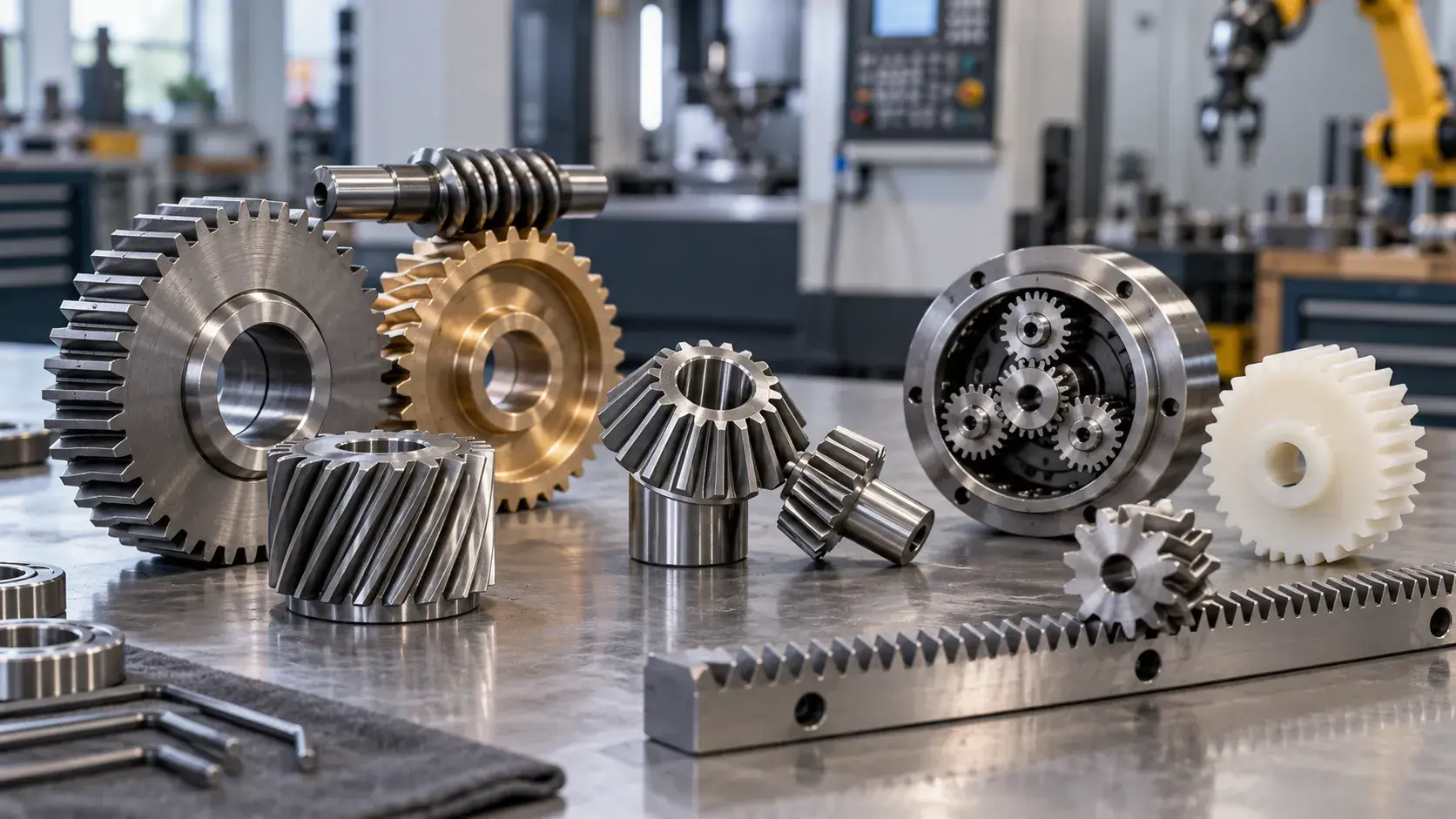
Spur gears are one of the simplest and most common gear types.
Their teeth are straight and parallel to the shaft.
Because of this simple geometry, spur gears are relatively easy to manufacture and provide high mechanical efficiency.
They work best between parallel shafts.
Advantages:
- High efficiency
- Simple design
- Easy to manufacture
- Lower production cost
Limitations:
- Can be noisy at high speed
- Tooth engagement is more sudden
Common applications:
Gearboxes, clocks, conveyors, machine tools, and simple mechanical systems.
Spur gears are often a good choice when cost, efficiency, and simplicity are more important than quiet operation.
2. Helical Gear
Helical gears have teeth cut at an angle rather than straight across the gear face.
This angled tooth design allows the teeth to engage gradually.
As a result, helical gears generally run more smoothly and quietly than spur gears.
They are widely used in higher-speed or higher-load applications.
Advantages:
- Smooth operation
- Lower noise
- Higher load capacity than spur gears
- Good for high-speed applications
Limitations:
- Produces axial thrust
- More complex to manufacture
- Slightly higher friction
Common applications:
Automotive transmissions, industrial gearboxes, compressors, pumps, and high-speed machinery.
If two parallel shafts need to transmit significant power with less noise, a helical gear is often a better choice than a spur gear.
3. Herringbone Gear
Herringbone gears, also called double helical gears, use two sets of angled teeth arranged in opposite directions.
This design helps cancel the axial forces that occur in a single helical gear.
They are commonly used in heavy-duty transmission systems.
Advantages:
- High load capacity
- Smooth power transmission
- Reduced axial thrust
- Suitable for heavy machinery
Limitations:
- More difficult to manufacture
- More expensive
- Requires high manufacturing accuracy
Common applications:
Marine drives, heavy industrial gearboxes, turbines, compressors, and large machinery.
4. Bevel Gear
Bevel gears transmit power between shafts that intersect, commonly at 90 degrees.
Instead of a cylindrical shape, the gear teeth are formed on a conical surface.
There are several forms of bevel gears, including straight bevel and spiral bevel gears.
Advantages:
- Changes the direction of power transmission
- Compact layout
- Available for different speed and torque requirements
Limitations:
- Requires accurate alignment
- More complex than spur gears
- Contact pattern is important for smooth operation
Common applications:
Automotive differentials, hand tools, marine equipment, industrial drives, and right-angle gearboxes.
5. Worm Gear
A worm gear system consists of a screw-shaped worm and a larger worm wheel.
The shafts are usually arranged at 90 degrees without intersecting.
One of the main advantages of worm gearing is its ability to achieve a large reduction ratio in a compact space.
Advantages:
- High gear reduction
- Compact design
- Smooth and quiet operation
- Can resist back-driving in some designs
Limitations:
- Lower efficiency due to sliding friction
- Generates more heat
- Requires proper lubrication
Common applications:
Lifts, conveyors, gates, positioning systems, and industrial machinery.
Worm gears are useful when speed needs to be reduced significantly while increasing torque.
6. Rack and Pinion
A rack and pinion system combines a round gear, called the pinion, with a straight toothed bar called the rack.
Instead of simply transferring rotary motion, the system converts rotary motion into linear movement.
Advantages:
- Simple motion conversion
- Accurate positioning
- Long travel possible
- Efficient mechanical design
Limitations:
- Backlash can affect positioning accuracy
- Teeth may require protection from contamination
Common applications:
Automotive steering systems, CNC machines, automation equipment, linear motion systems, and industrial positioning equipment.
7. Internal Gear
Internal gears have teeth on the inside of a ring rather than around the outside.
They usually mesh with a smaller external gear located inside the ring.
This design is commonly used when a compact gear system is required.
Advantages:
- Compact arrangement
- Useful for planetary systems
- High contact ratio
- Can transmit significant torque
Limitations:
- Manufacturing is more difficult than external gears
- Tool access can be limited
Common applications:
Planetary gearboxes, transmissions, robotics, and compact industrial drives.
8. Planetary Gear
A planetary gear system consists of a central sun gear, several planet gears, and an outer ring gear.
The planet gears rotate around the sun gear while also rotating on their own axes.
This arrangement allows a large amount of torque to be transmitted through a compact gearbox.
Advantages:
- High torque density
- Compact size
- Multiple gear ratios possible
- Load distributed across several gears
Limitations:
- More complex design
- Requires precise manufacturing
- Assembly accuracy is important
Common applications:
Robotics, electric vehicles, industrial automation, aerospace systems, servo gearboxes, and power tools.
Planetary gear systems are especially useful when high torque is needed in a limited space.
9. Hypoid Gear
Hypoid gears are similar to spiral bevel gears, but their shafts do not intersect.
Instead, the shaft axes are offset.
This allows smoother tooth engagement and greater design flexibility.
Advantages:
- Smooth operation
- High torque capacity
- Compact layout
- Suitable for offset shafts
Limitations:
- Greater sliding friction
- Requires good lubrication
- More difficult to manufacture
Common applications:
Automotive differentials, axle drives, and high-torque power transmission systems.
10. Screw Gear
Screw gears, sometimes called crossed helical gears, are used between non-parallel and non-intersecting shafts.
They have angled teeth similar to helical gears.
However, they usually carry lighter loads because the tooth contact area is relatively small.
Advantages:
- Simple crossed-shaft arrangement
- Smooth operation
- Flexible shaft positioning
Limitations:
- Limited load capacity
- More sliding contact
- Lower efficiency than spur or helical gears
Common applications:
Light-duty machinery, instruments, feeding systems, and small transmission mechanisms.
How to Choose the Right Gear Type
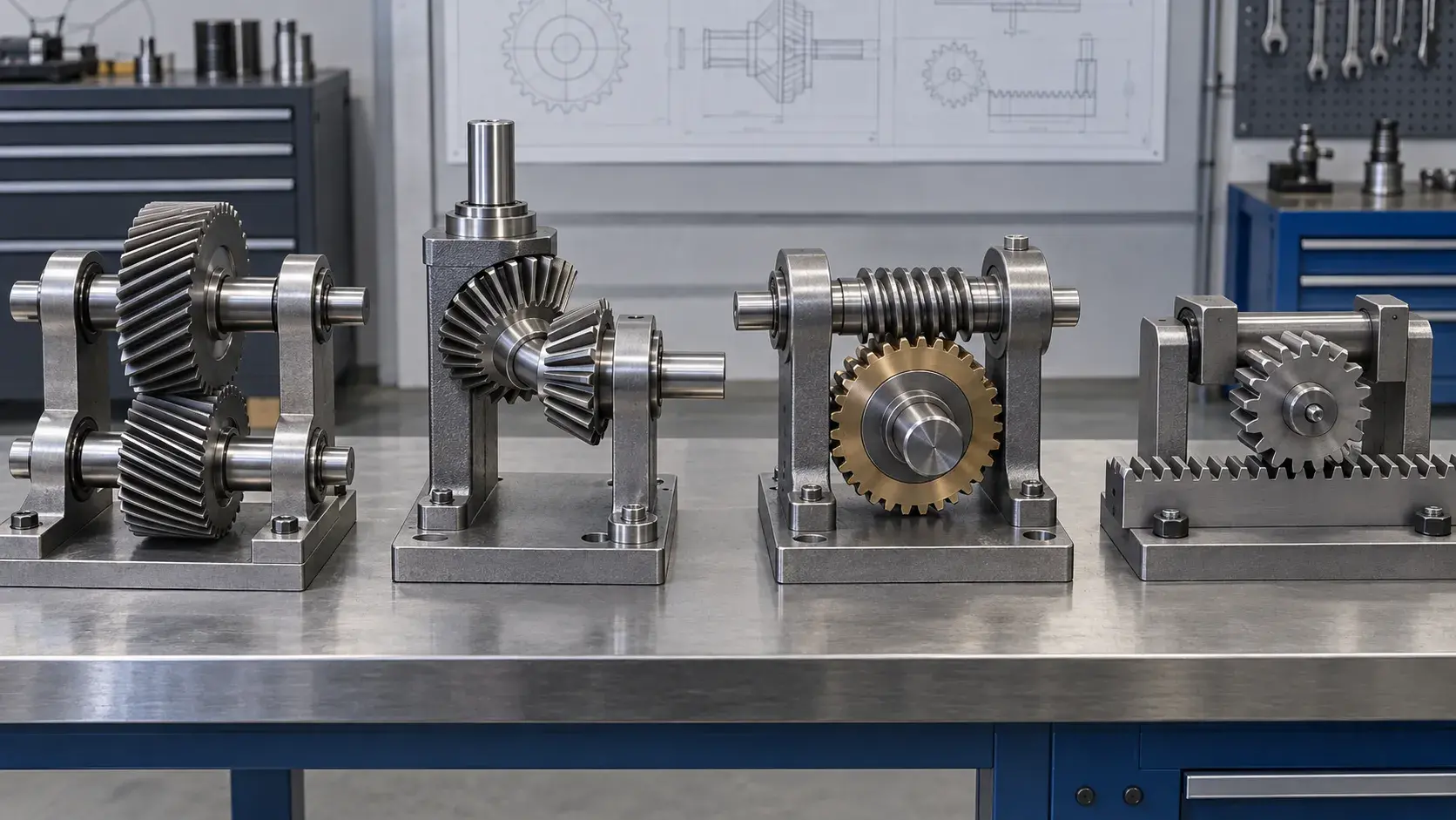
The easiest way to choose a gear is to start with the system requirements rather than the gear name.
Shaft Arrangement
This is usually the first decision.
For parallel shafts, common choices include:
- Spur gears
- Helical gears
- Herringbone gears
For intersecting shafts:
- Bevel gears
For non-parallel and non-intersecting shafts:
- Worm gears
- Hypoid gears
- Screw gears
For rotary-to-linear motion:
- Rack and pinion
Speed and Noise
Spur gears are efficient but can become noisy at higher speeds.
Helical gears engage more gradually and are usually better when quieter operation is required.
For very smooth high-speed transmission, spiral bevel or helical designs may be more suitable.
Load and Torque
For higher loads, helical and herringbone gears generally perform better than simple spur gears.
Planetary gear systems are useful when high torque needs to be transmitted in a compact space.
Gear Ratio
If a large speed reduction is needed, worm gears and planetary gear systems are common choices.
A spur or helical gear pair is usually better when only a moderate ratio is required.
Available Space
Space is especially important in compact machinery.
Planetary gear systems provide high torque density, while internal gears can reduce overall gearbox size.
Motion Type
If the system needs linear movement rather than rotational output, rack and pinion is usually the most direct solution.
Basic Gear Design Parameters
You do not need to understand every gear calculation to compare different gear types, but several basic parameters are important.
Module
Module describes the size of the gear teeth.
A larger module generally means larger and stronger teeth.
Number of Teeth
The number of teeth affects gear size and gear ratio.
When two gears mesh, their tooth counts help determine the output speed.
Gear Ratio
The gear ratio determines how rotational speed and torque change between input and output.
For a simple gear pair:
Gear Ratio = Number of Teeth on Driven Gear ÷ Number of Teeth on Driving Gear
A higher ratio generally reduces output speed while increasing torque.
Pressure Angle
Pressure angle affects how force is transmitted between gear teeth.
Common pressure angles are standardized, and the correct value depends on the gear system and design requirements.
Pitch Diameter
Pitch diameter is a theoretical diameter used to calculate gear geometry and tooth engagement.
It is one of the main dimensions used when designing a gear pair.
What Materials Are Used for Gears?
The best material depends on load, speed, wear, noise, environment, and cost.
Common gear materials include:
Used for high-strength and high-load gears.
Common examples include alloy steels and hardened steels.
Used when corrosion resistance is important.
Suitable for lightweight, moderate-load applications.
Often used in worm gears and applications requiring good wear behavior.
Engineering Plastics
Materials such as POM, nylon, and PEEK are used for low-noise, lightweight, corrosion-resistant gears.
Plastic gears are common in instruments, automation equipment, medical devices, and light-duty mechanisms.
How Are Gears Manufactured?
Different gear geometries require different manufacturing processes.
Gear Hobbing
Hobbing is one of the most common methods for producing external spur and helical gears.
A rotating cutting tool called a hob progressively cuts the gear teeth.
It is efficient for production quantities.
Gear Shaping
Gear shaping uses a reciprocating gear-shaped cutter.
It is especially useful for internal gears or areas where hobbing cannot reach.
Gear Milling
Gear teeth can also be produced using CNC milling machines.
This method is useful for prototypes, low-volume parts, large gears, and custom geometries.
5-Axis CNC Machining
5-axis machining can produce complex gear-related features and special geometries without many setups.
It is particularly useful for prototypes and customized components.
Gear Grinding
Grinding is used after heat treatment when high accuracy, smooth tooth surfaces, and low noise are required.
In many production applications, gear manufacturing uses a combination of machining, heat treatment, and finishing processes.
Can Gears Be CNC Machined?
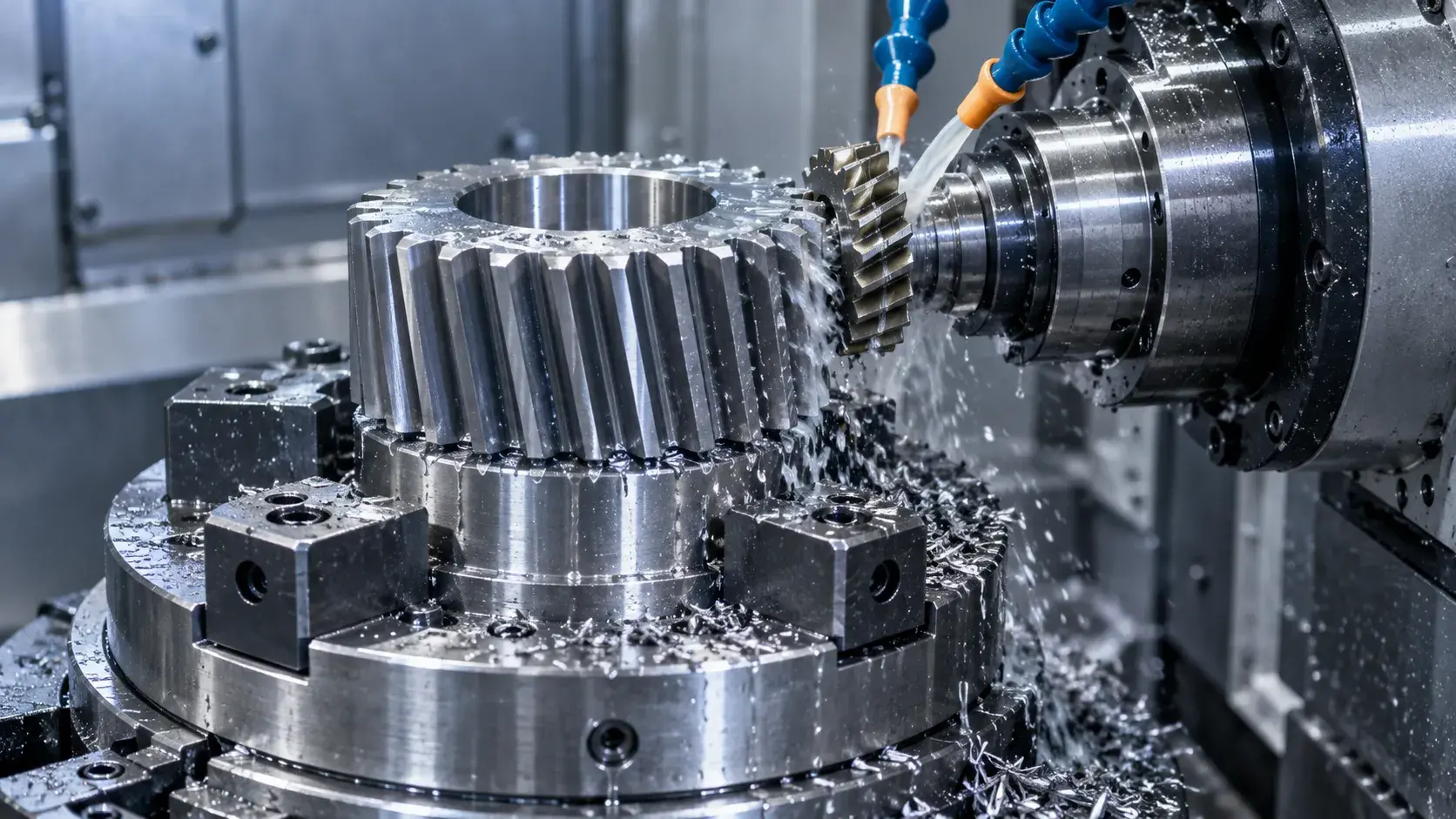
Yes.
CNC machining is commonly used for custom and low-volume gears, especially when standard off-the-shelf gears cannot meet the design requirements.
CNC milling can produce spur gears, some bevel gears, gear segments, racks, and specialized tooth forms.
It is particularly useful for:
- Prototypes
- Small production batches
- Custom dimensions
- Large gear components
- Special materials
- Integrated gear features
However, high-volume standard gears are often more efficiently produced using dedicated processes such as hobbing or shaping.
The best manufacturing method depends on gear geometry, quantity, accuracy requirement, and material.
Conclusion
Different types of gears are designed for different transmission requirements.
Spur gears are simple and efficient. Helical gears are smoother and quieter. Bevel gears change transmission direction, while worm and planetary systems can provide large reduction ratios or high torque in compact spaces.
Rack and pinion systems are useful when rotary motion must be converted into linear movement.
When selecting a gear, consider shaft arrangement, speed, load, noise, gear ratio, available space, and manufacturing method.
The best gear is not the most complex one. It is the one that meets the mechanical requirements with the simplest and most reliable design.



