

A fillet creates a rounded transition between two surfaces, while a chamfer removes a sharp corner with a flat angled surface. In mechanical design, fillets are commonly used to reduce stress concentration, create smooth transitions, and accommodate CNC cutter geometry. Chamfers are more often used for edge breaking, deburring, hole entrances, and assembly lead-ins.
For CNC machined parts, the choice is not only about appearance. Fillet radius, chamfer size, tool accessibility, pocket depth, material, and tolerance can all affect machining time and cost.
| Feature | Fillet | Chamfer |
|---|---|---|
| Geometry | Rounded radius | Flat angled face |
| Typical dimension | Radius, such as R3 | Width and angle, such as 1 × 45° |
| Stress reduction | Very good | Moderate |
| Internal CNC corners | Common | Less common |
| Assembly lead-in | Limited | Very good |
| Edge breaking | Possible | Very common |
| Machining complexity | Depends on location and radius | Usually straightforward |
| Typical applications | Loaded corners, pockets, smooth transitions | Holes, shafts, edges, assembly features |
What Is the Difference Between a Fillet and a Chamfer?
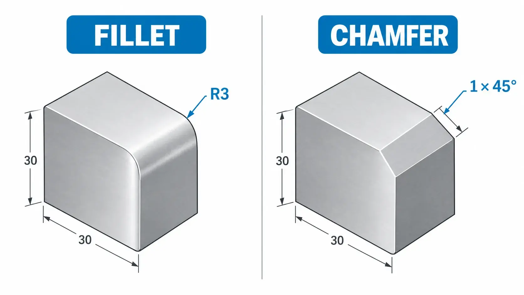
The main difference between a fillet and a chamfer is the shape created at the intersection of two surfaces.
A fillet replaces a sharp corner with a curved surface defined by a radius. For example, an R3 fillet has a 3 mm radius.
A chamfer replaces the corner with a straight angled face. A common callout such as 1 × 45° indicates a 1 mm chamfer at a 45-degree angle.
Although both features remove sharp corners, they serve different engineering purposes.
Fillets are often preferred where stress needs to flow smoothly through a component. Chamfers are commonly used where a simple edge break or assembly lead-in is required.
In CNC machining, another major difference is that internal fillets are often influenced directly by the geometry of the cutting tool.
What Is a Fillet?
A fillet is a rounded transition between two intersecting surfaces.
Fillets may appear on internal corners, external edges, or between a wall and the floor of a machined pocket.
Common types include:
- Internal corner fillet — a radius inside a pocket or cavity.
- Bottom fillet — a radius between a vertical wall and horizontal floor.
- External fillet — a rounded outside edge.
- Structural fillet — a radius added to reduce stress concentration in a loaded component.
Fillets are widely used in aerospace brackets, robotic components, housings, fixtures, and other machined parts where sharp transitions could increase stress or be difficult to manufacture.
What Is a Chamfer?
A chamfer is a flat angled surface created by removing a sharp corner.
The most common chamfer angle is 45°, but other angles such as 30° or 60° may also be specified depending on the application.
Typical chamfer applications include:
- Breaking sharp edges
- Removing machining burrs
- Creating a lead-in for shafts or pins
- Helping screws enter holes
- Preparing threaded holes
- Improving assembly
- Protecting exposed edges
Chamfers are generally simple to machine using chamfer mills, countersink tools, spot drills, or standard milling cutters depending on the feature geometry.
Fillet vs Chamfer: Key Differences
The correct choice depends on the function of the feature rather than appearance alone.
| Design Factor | Fillet | Chamfer |
|---|---|---|
| Surface shape | Curved | Flat |
| Stress distribution | Smoother | Less effective than a radius |
| Fatigue-sensitive parts | Often preferred | Less common |
| Pocket corners | Very common | Uncommon |
| Deburring | Possible | Very common |
| Assembly lead-in | Possible | Usually better |
| Shaft end | Sometimes used | Very common |
| Hole entrance | Sometimes used | Very common |
| CNC tool limitation | Important for internal radii | Usually less restrictive |
| Inspection | Radius gauge, CMM, profile inspection | Caliper, comparator, CMM |
| Cost impact | Highly dependent on radius and geometry | Often relatively simple |
The important point is that neither feature is automatically better. The correct choice depends on stress, function, assembly requirements, tool access, and manufacturing cost.
How Fillets Are Machined in CNC Parts
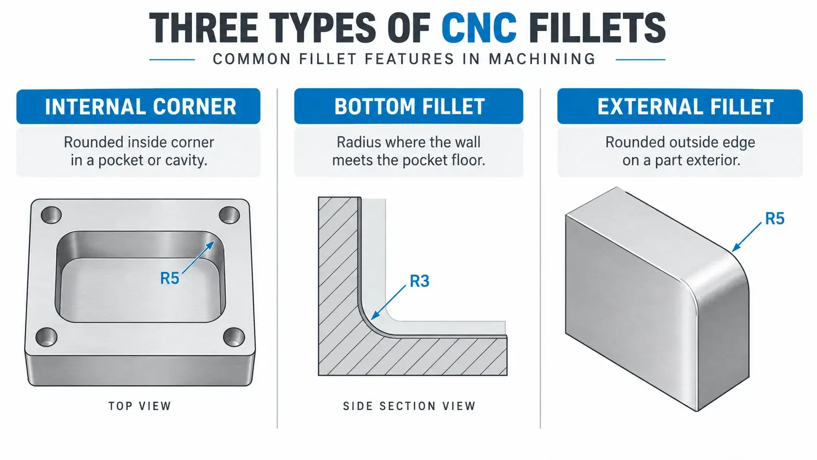
Not all fillets are machined in the same way.
This distinction is important because the location of the radius determines which cutting tool can be used.
Internal Corner Fillets
An internal corner fillet is commonly found in CNC-milled pockets.
Because a standard end mill is cylindrical, it naturally leaves a radius in the internal corner. A perfectly sharp 90-degree internal corner therefore cannot normally be produced with conventional milling.
For example, a 10 mm diameter end mill has a 5 mm tool radius.
The theoretical minimum internal corner radius produced by that tool is approximately:
R5 mm
However, designing the part with exactly the same radius as the cutter is usually not ideal.
When the cutter radius and part radius are identical, a large portion of the tool may contact the corner at the same time. This can increase tool engagement, vibration, heat, and machining load.
For this reason, designers should usually allow the internal corner radius to be somewhat larger than the cutter radius.
For example:
R6 mm internal corner + Ø10 mm end mill
is generally more machining-friendly than:
R5 mm internal corner + Ø10 mm end mill
because the tool can follow a smoother path through the corner.
Bottom Fillets
A bottom fillet is located where a vertical wall meets the floor of a pocket.
Unlike a vertical internal corner radius, this feature may require a different cutting tool or finishing operation.
Depending on the geometry, manufacturers may use:
- Bull nose end mills
- Corner radius end mills
- Ball nose end mills
- 3D contour milling
Bottom fillets should therefore be specified only where they provide a functional or structural benefit.
Adding very small bottom radii unnecessarily can increase tooling requirements and machining time.
External Fillets
External fillets are rounded outside edges.
They can often be machined using:
- Corner-rounding cutters
- Ball nose end mills
- Form tools
- Multi-axis contour machining
External fillets are usually less restricted by tool diameter than internal pocket corners because the cutter can approach the feature from outside the part.
For complex external surfaces, 5-axis CNC machining can provide better tool access and smoother transitions.
How Chamfers Are Machined
Chamfers are generally straightforward CNC features.
Common tools include:
- Chamfer mills
- Countersink cutters
- Spot drills
- End mills
- Turning tools
A 45-degree chamfer tool can often machine several edges in one setup, which makes chamfers efficient for edge breaking and deburring.
On turned parts, chamfers can also be produced directly using the turning tool.
Because chamfers are straight rather than curved, their toolpaths are usually simpler than complex 3D fillet surfaces.
However, chamfers are not always cheaper.
Cost still depends on factors such as:
- Number of edges
- Part orientation
- Tool accessibility
- Required tolerance
- Whether an additional setup is needed
- Whether the chamfer is functional or cosmetic
How Fillet Radius Affects CNC Machining Cost
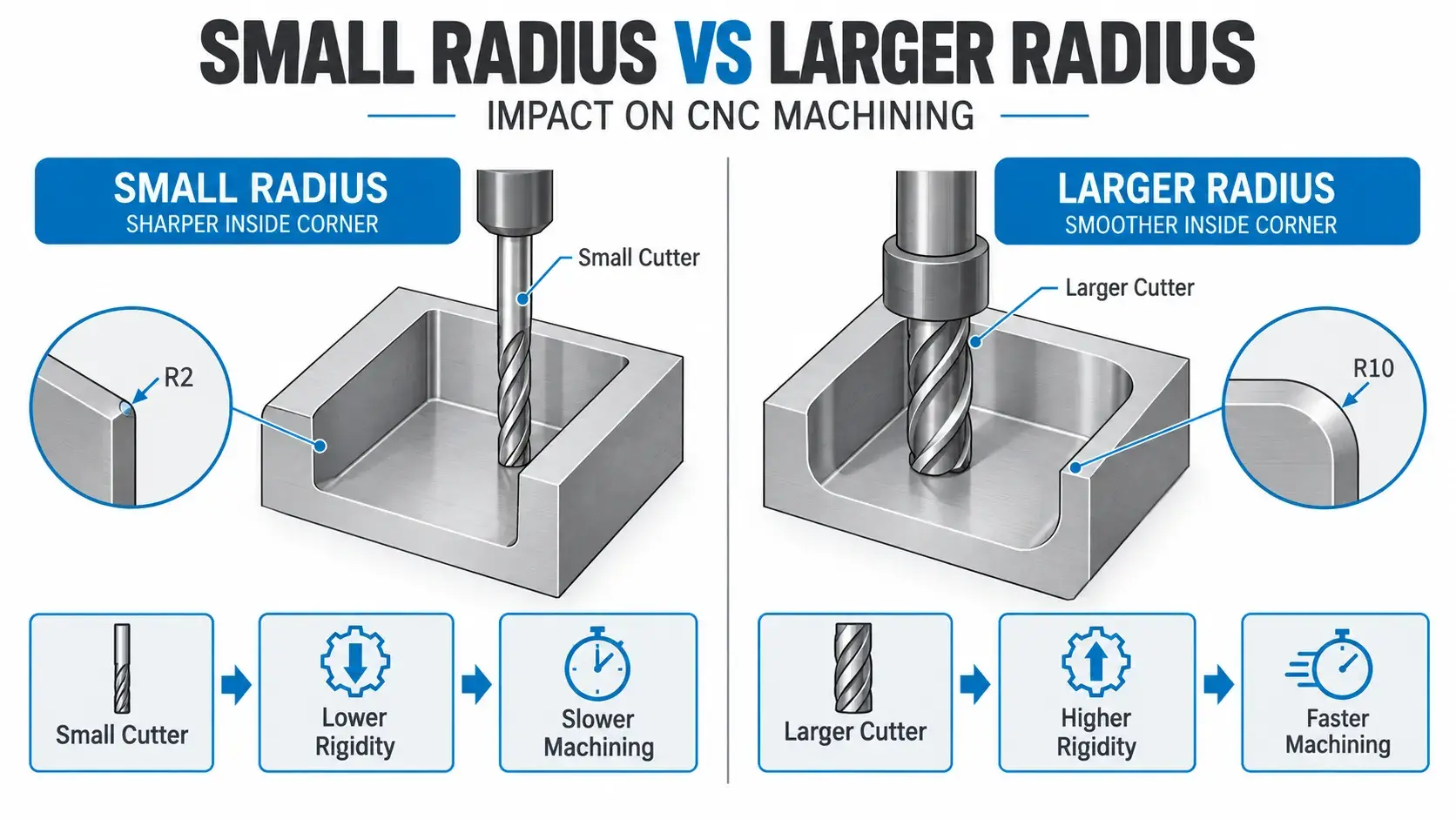
Fillet radius can have a significant effect on CNC machining cost, especially inside deep pockets.
A smaller internal radius usually requires a smaller cutter.
This often creates the following relationship:
Smaller radius → smaller end mill → lower rigidity → lower feed rate → longer machining time
A larger radius may allow a larger and more rigid cutter:
Larger radius → larger cutter → higher rigidity → higher material removal rate → shorter cycle time
This does not mean that every larger radius is automatically cheaper. Geometry, pocket depth, material, machine configuration, and tolerance still matter.
But as a general DFM principle, designers should avoid specifying unnecessarily small internal radii.
Example
Suppose a pocket contains an R2 internal corner.
The cutter must generally have a radius smaller than R2, meaning the cutter diameter must be less than approximately 4 mm.
If that pocket is deep, the small cutter may require a long tool extension.
This can increase:
- Deflection
- Vibration
- Risk of tool breakage
- Finishing passes
- Cycle time
Changing the internal radius to R4 or R5 may allow a substantially larger cutter and simplify machining.
Fillet Radius vs Tool Diameter
There is no single universal cutter size for every internal radius.
A practical cutter choice depends on pocket depth, material, tool length, wall thickness, surface finish, and machine rigidity.
The following table is only an illustrative guide.
| Internal Corner Radius | Approximate Cutter Limitation | DFM Consideration |
|---|---|---|
| R2 mm | Cutter diameter below Ø4 mm | Small cutter may increase machining time |
| R3 mm | Cutter diameter below Ø6 mm | Suitable for moderate-detail features |
| R5 mm | Cutter diameter below Ø10 mm | Allows larger, more rigid tools |
| R8 mm | Cutter diameter below Ø16 mm | More machining-friendly for larger pockets |
In practice, manufacturers often prefer a cutter radius smaller than the specified part radius rather than matching the radius exactly.
The deeper the pocket, the more important this becomes.
If the part function allows it, using the largest practical internal corner radius is generally one of the simplest ways to improve CNC machinability.
When Should You Use a Fillet?
A fillet is usually the better choice when the design requires smooth stress transfer or an internal CNC-machined corner.
Common situations include:
Stress-Concentrated Areas
Sharp corners can create high local stress.
Adding a fillet allows load to flow more gradually through the material and can improve fatigue performance.
This is especially important for:
- Aerospace brackets
- Robotic arms
- Structural supports
- Machine fixtures
- Repeated-load components
CNC-Milled Pockets
Internal radii are a natural result of end milling.
Instead of specifying a sharp internal corner, design a suitable fillet radius that allows practical tool access.
Smooth External Transitions
External fillets are useful where a rounded transition improves handling, appearance, or part strength.
When Should You Use a Chamfer?
Chamfers are generally better when the feature is intended to guide assembly, remove sharp edges, or prepare an opening.
Assembly Lead-Ins
Chamfers help align mating components such as:
- Pins
- Shafts
- Bearings
- Bushings
- Fasteners
A chamfer allows the mating component to enter gradually instead of hitting a sharp edge.
Hole Entrances
Chamfers around drilled holes help:
- Remove burrs
- Guide screws
- Start threads
- Protect hole edges
Where the feature is designed specifically to seat a flat-head screw, a countersink may be more appropriate than a simple chamfer.
Edge Breaking
Small chamfers are commonly used to eliminate sharp machined edges.
Typical edge-break chamfers may be relatively small because their main purpose is safety and deburring rather than structural performance.
Fillet vs Chamfer for Different Design Requirements
| Requirement | Recommended Feature |
|---|---|
| Reduce stress concentration | Fillet |
| Improve fatigue resistance | Fillet |
| CNC pocket corner | Fillet |
| Smooth structural transition | Fillet |
| Remove sharp edges | Chamfer |
| Shaft lead-in | Chamfer |
| Pin insertion | Chamfer |
| Hole entrance | Chamfer |
| General deburring | Chamfer |
| Rounded cosmetic edge | Fillet |
| Fast, simple edge machining | Chamfer |
These are general guidelines rather than fixed rules.
For example, a rounded edge can also be used for safety or appearance, while a chamfer may sometimes be selected for structural packaging reasons.
How to Specify Fillets and Chamfers on Engineering Drawings
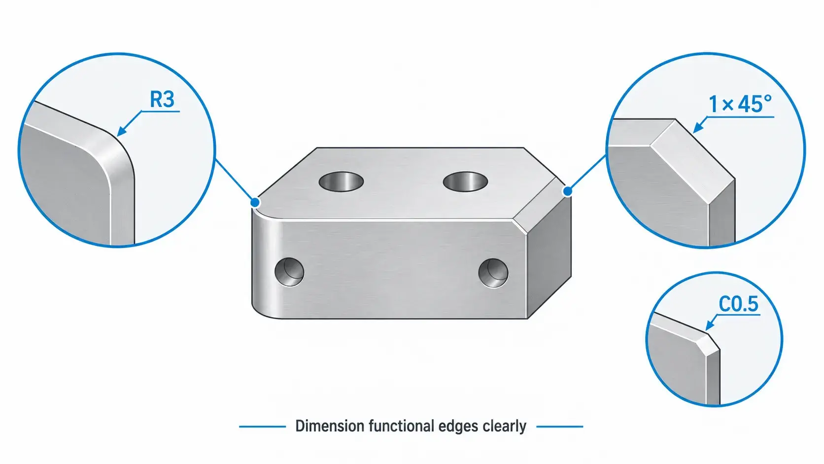
Clear drawing specifications help prevent machining errors and unnecessary clarification.
Fillet Callout
Fillets are usually specified by radius.
For example:
R3
means a radius of 3 mm.
A drawing may also use a leader pointing directly to the rounded surface.
Chamfer Callout
A chamfer may be specified using size and angle.
For example:
1 × 45°
means a 1 mm chamfer at 45 degrees.
Some drawings may also use callouts such as:
C0.5
for a small standard chamfer, depending on the drawing convention.
For functional chamfers, it is better to specify the required size clearly rather than rely only on a general note such as:
Break sharp edges
This is especially important when the chamfer affects:
- Assembly
- Sealing
- Thread engagement
- Bearing installation
- Final dimensions
For more complex drawings, standardized engineering drawing symbols and GD&T controls can further define part requirements.
Common Fillet and Chamfer Design Mistakes
1. Specifying an Unnecessarily Small Internal Radius
A small radius may force the manufacturer to use a much smaller end mill, increasing machining time and cost.
Use the largest radius that the part function allows.
2. Designing Sharp Internal Corners
Conventional CNC milling cannot normally produce a perfectly sharp internal 90-degree corner with a cylindrical end mill.
If a mating rectangular component must fit inside the pocket, alternative designs such as reliefs or dog-bone corners may be needed.
3. Matching the Fillet Radius Exactly to the Cutter Radius
Designing an R5 internal corner specifically for a Ø10 mm cutter can increase cutter engagement in the corner.
A slightly larger radius usually provides a more efficient toolpath.
4. Adding Fillets Everywhere
Fillets should have a purpose.
Unnecessary radii may add tool changes, 3D finishing operations, or additional inspection.
5. Over-Tolerancing Chamfers
A small edge-break chamfer usually does not require the same tight tolerance as a critical mating dimension.
Unnecessarily tight chamfer tolerances increase inspection and machining effort.
6. Confusing a Chamfer With a Countersink
A chamfer is a general angled edge feature.
A countersink is typically a conical feature around a hole designed for a specific fastener or function.
If screw seating is important, specify the countersink geometry directly.
Fillet vs Chamfer: Which One Should You Choose?
Choose a fillet when you need smoother stress distribution, better fatigue performance, a rounded transition, or a machinable internal CNC corner.
Choose a chamfer when you need an assembly lead-in, edge break, deburring feature, or angled hole entrance.
For CNC-milled pockets, the most important DFM rule is simple:
Use the largest practical internal radius that does not interfere with part function.
This can allow larger cutting tools, improve tool rigidity, shorten machining time, and reduce cost.
The final choice should always consider part function, material, loading, tooling, tolerance, and accessibility rather than treating fillets or chamfers as purely cosmetic features.
FAQ
A fillet generally provides smoother stress distribution because it avoids an abrupt geometric transition. For fatigue-loaded or highly stressed parts, a suitable fillet is often preferred. The actual strength improvement depends on the radius, material, load direction, and surrounding geometry.
CNC milling cutters are cylindrical, so the cutter naturally leaves a radius in an internal corner. Producing a perfectly sharp inside corner usually requires another manufacturing process or a special relief design.
A 45-degree chamfer is very common for general edge breaking and assembly features. Other angles may be specified depending on the design requirement.
There is no single standard radius. As a general DFM principle, use the largest internal radius that the design allows. Larger radii usually permit larger, more rigid tools and can reduce machining time.
Often, but not always. Simple chamfers are usually easy to machine, while complex fillets may require additional tooling or 3D toolpaths. However, cost depends on feature location, accessibility, tool changes, radius size, and setup requirements.
Standard end milling cannot create a perfectly sharp internal corner because the cutter has a finite radius. If a sharp corner is functionally necessary, techniques such as EDM, broaching, or corner reliefs may be considered.



