

Machining large parts requires more than a CNC machine with enough travel. As part size increases, workholding, tool reach, thermal stability, machine rigidity, chip evacuation, datum control, and inspection all become more difficult to manage.
The right process depends on the workpiece size, weight, geometry, material, tolerance requirements, and how many sides must be machined. Vertical, horizontal, gantry, turning, and 5-side machining each solve different problems, so process selection should be based on the part rather than the machine alone.
What Makes Machining Large Parts Different?
Machining large parts becomes more difficult because dimensional errors, deflection, temperature changes, and setup problems accumulate over a much larger physical distance.
A part may be considered large because of its:
- Overall length or width
- Diameter
- Weight
- Required machine travel
- Fixture size
- Tool reach
- Handling requirements
A long aluminum frame, large machine base, aerospace structural component, and large-diameter shaft may all require different strategies.
The challenge is not simply fitting the part on the machine.
The real challenge is keeping the workpiece stable, accurately referenced, and measurable throughout the entire machining process.
Which CNC Processes Are Used for Large Parts?
The most suitable process depends mainly on part geometry and required access.
Common processes include:
- Large part vertical machining
- Horizontal CNC machining
- Gantry machining
- 5-side machining
- Large part CNC turning
- Drilling and boring
- Multi-axis finishing
Large prismatic parts are usually machined by milling, while rotational parts such as shafts and rollers are typically turned.
Some components require more than one process.
For example, a large cylindrical housing may first be turned to establish its main diameter and then transferred to a milling machine for bolt patterns, slots, or side features.
Large Part Vertical Machining
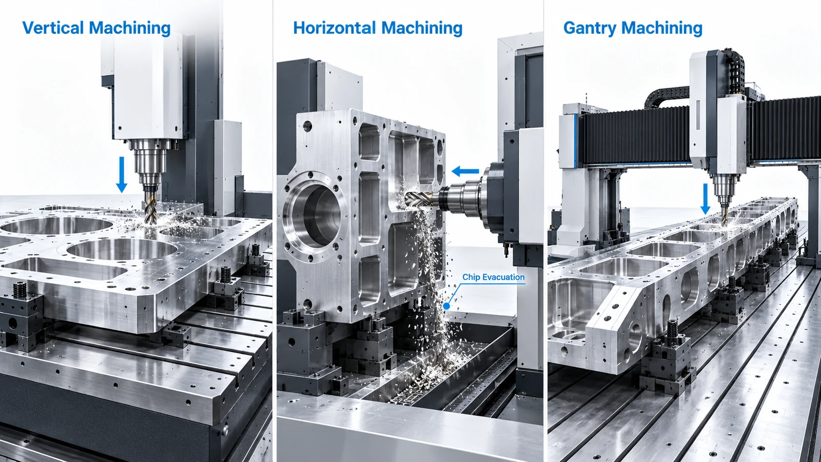
Large part vertical machining is well suited to plates, machine bases, housings, frames, molds, and other components that can be supported on a broad horizontal table.
Advantages include:
- Straightforward workholding
- Good access to top surfaces
- Easy visual setup
- Stable support for long or heavy parts
For extra large part vertical machining, however, machine travel and spindle clearance become critical.
The part may physically fit on the table but still be difficult to machine if the spindle, toolholder, fixture, or machine structure cannot reach required features safely.
Vertical machining works best when most critical features can be accessed from above or through a manageable number of indexed orientations.
When Is Horizontal Machining Better for Large Parts?
Horizontal machining can be useful when the component requires significant side access or produces large amounts of chips.
With a horizontal spindle, gravity helps chips fall away from the cutting zone instead of collecting inside deep pockets.
This can improve:
- Chip evacuation
- Tool life
- Surface quality
- Process stability
For extra large part horizontal CNC machining, the machine must also provide enough pallet capacity, fixture space, spindle reach, and rotary clearance.
Horizontal machining can be especially useful for large box-shaped components and deep side features.
However, it is not automatically better than vertical machining.
The correct choice depends on which machine orientation reduces setups and improves access to the most important features.
When Should Gantry Machining Be Used?
Gantry machining is often selected for long, wide, or heavy components that are difficult to support or position on conventional machining centers.
Typical applications include:
- Long structural parts
- Machine frames
- Large aluminum plates
- Aerospace structures
- Mold bases
- Industrial equipment components
A gantry configuration allows the workpiece to remain supported on a large table while the bridge and spindle move over the part.
This is especially useful when the component is too large or too heavy to rotate conveniently.
For oversized parts, the main benefit is not simply a larger machine.
It is the combination of:
- Large work envelope
- Stable support
- Long-axis travel
- Flexible spindle access
When a part exceeds the practical limits of a standard vertical machining center, gantry machining may provide a more suitable process.
For actual machine capacity and large-format service capability, readers can refer to YUANYI’s Gantry CNC Machining Services page.
How Does 5-Side Machining Reduce Setups?
Some large parts require machining on the top and multiple side faces.
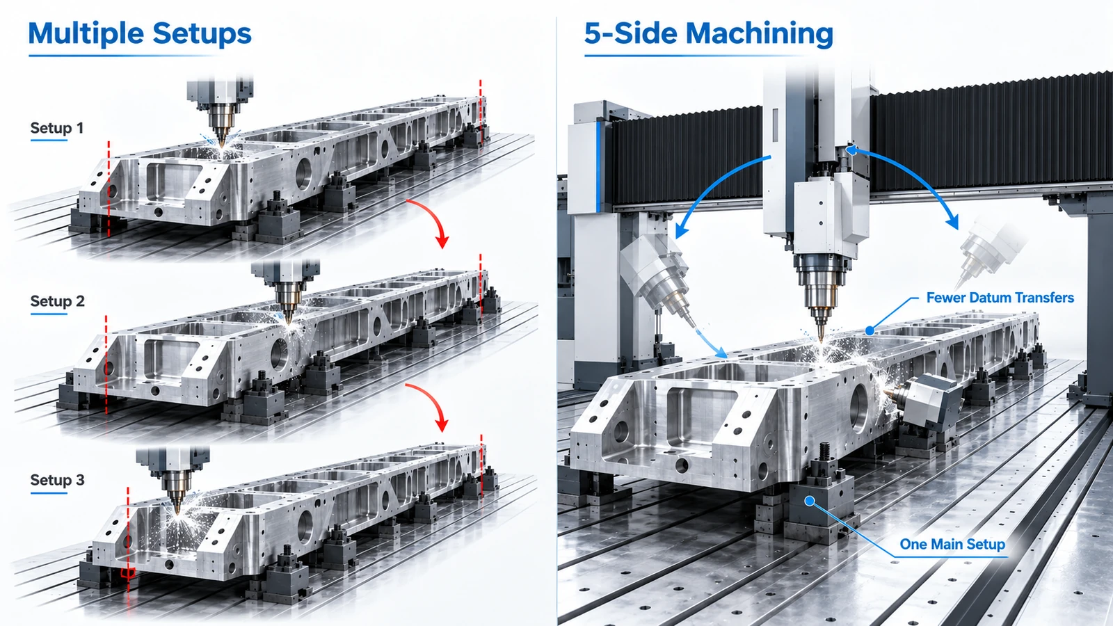
A conventional process may require:
- Machine the top.
- Remove the part.
- Reposition it.
- Re-establish the datum.
- Machine another side.
- Repeat for additional faces.
Each repositioning introduces more handling and another opportunity for alignment error.
Large part 5-side vertical machining can reduce these repeated setups.
Instead of rotating the entire workpiece, an articulating spindle head or multi-axis system can approach multiple faces while the component remains fixed.
This can reduce:
- Manual repositioning
- Fixture changes
- Datum transfers
- Alignment time
Not every large component requires simultaneous 5-axis machining.
For many parts, 3+2 or indexed machining is sufficient.
The spindle moves to the required angle, then the cutting operation proceeds with the rotary axes stationary.
This can provide a simpler and more stable solution for angled holes, planar faces, and side features.
Large Part CNC Turning
Large part CNC turning is used for rotational components such as:
- Shafts
- Rollers
- Flanges
- Large bushings
- Cylindrical housings
- Rotating equipment parts
Important factors include:
- Maximum swing diameter
- Turning length
- Workpiece weight
- Chuck capacity
- Tailstock support
- Steady-rest requirements
- Part balance
Long shafts can deflect under their own weight and cutting force.
Large-diameter parts also generate higher rotational forces, so workholding and spindle speed must be selected carefully.
If the part also requires milling features, the process plan should compare separate turning and milling operations with mill-turn machining.
What Makes Large Part Precision Machining Difficult?
Large part CNC precision machining becomes challenging because small process errors can create larger dimensional effects over long distances.
Workpiece Deflection
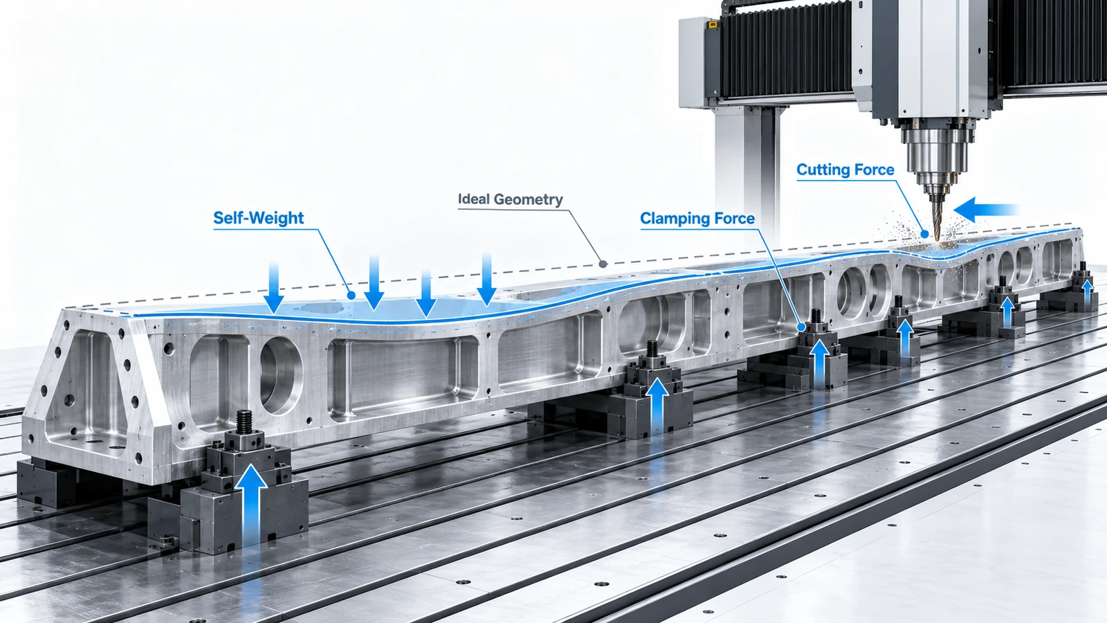
Large plates, rails, and frames may sag under their own weight.
Cutting force and clamp pressure can create additional deformation.
A part may measure correctly while clamped but change shape after it is released.
Thermal Expansion
Temperature changes can affect both the workpiece and the machine.
On a large component, even small temperature changes can produce measurable dimensional variation across long distances.
This is especially important when tight tolerances are required between widely separated features.
Tool Reach
Deep features or tall geometry may require long cutting tools.
Long tools reduce rigidity and increase the risk of:
- Deflection
- Chatter
- Poor surface finish
- Dimensional variation
A better spindle orientation or different setup can sometimes reduce the required tool length.
Chip Evacuation
Large pockets produce large chip volumes.
If chips remain in the cutting zone, they may be recut and damage the tool or surface.
Coolant delivery, machine orientation, and toolpath strategy all affect chip removal.
How Should Large Parts Be Set Up and Clamped?
Workholding is one of the most important parts of machining large components.
The fixture must resist movement without distorting the workpiece.
Large parts may require:
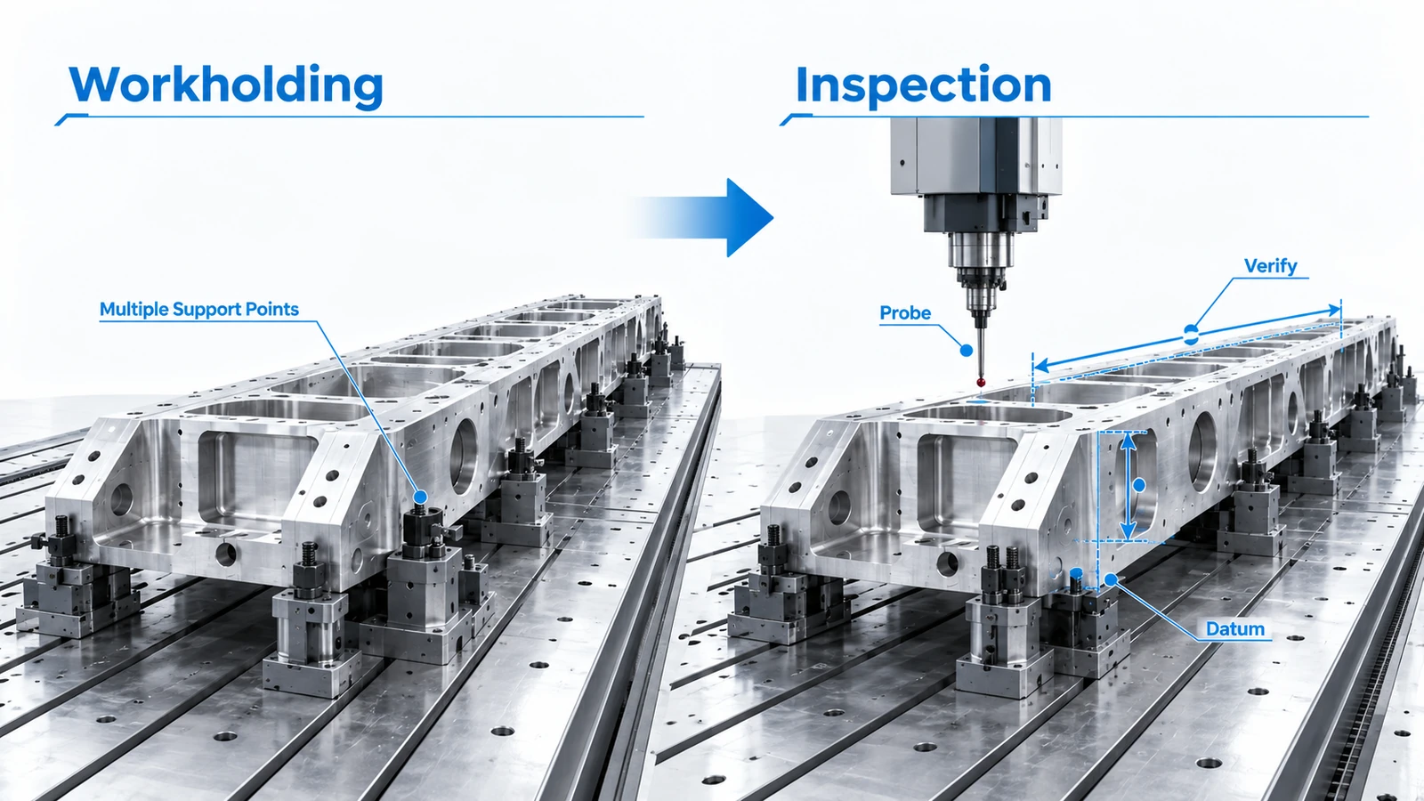
- Multiple support points
- Modular clamps
- Jack supports
- Custom fixtures
- Datum pins
- T-slot workholding
- Dedicated locating surfaces
Support should be distributed based on part stiffness and machining loads.
A common mistake is applying excessive clamping force to thin or flexible structures.
If the part is distorted during machining, the final dimensions may change after unclamping.
The setup should also provide stable datums that can be reused throughout multiple operations.
For long components, additional supports may be needed to reduce sag and vibration.
How Does Setup Strategy Affect Accuracy?
Setup strategy has a direct effect on dimensional consistency.
Every time a large part is removed, repositioned, and re-indicated, new alignment error can be introduced.
This is particularly important when features on different faces must maintain close positional relationships.
Reducing the number of setups can help reduce:
- Datum transfer errors
- Manual alignment
- Re-clamping variation
- Operator handling
However, fewer setups are only beneficial if tool access and workholding remain stable.
A one-setup strategy is not automatically better if it requires excessive tool reach or poor fixture support.
The correct setup is the one that balances:
Access, rigidity, datum control, and inspection.
How Are Tolerances Managed on Large Parts?
There is no universal tolerance for large CNC components.
Achievable tolerance depends on:
- Part size
- Material
- Geometry
- Machine condition
- Fixture stability
- Tool reach
- Temperature
- Inspection method
A tolerance that is straightforward over 20 mm may be much harder to maintain over 1,000 mm.
For this reason, designers should avoid applying unnecessarily tight tolerances to every dimension.
Critical mating features and datum relationships should receive tighter control, while non-critical dimensions can use appropriate general tolerances.
This can reduce:
- Machining time
- Inspection time
- Scrap risk
- Manufacturing cost
The most important dimensions are usually not the largest dimensions on the drawing, but the ones that affect assembly and function.
How Are Large Machined Parts Inspected?
Inspection should be planned before machining begins.
Large parts may not fit inside conventional measurement equipment, so the inspection method depends on size and tolerance requirements.
Common methods include:
- CMM inspection
- Portable measuring arms
- Laser measurement systems
- Height gauges
- Bore gauges
- Micrometers
- In-process probing
In-process probing can help verify:
- Datum position
- Critical bores
- Surface location
- Workpiece movement
- Intermediate dimensions
For very large parts, inspection while the workpiece remains on the machine can reduce handling and provide useful process feedback.
Portable measurement systems can also be used when the component cannot be moved easily to a fixed inspection area.
Design Considerations for Machining Large Parts
Design decisions have a major effect on manufacturability.
Avoid Excessively Deep Narrow Features
Deep narrow pockets require long tools and slower cutting conditions.
Where possible, increase feature width or reduce depth.
Use Practical Internal Radii
Very small internal radii require small cutters.
On a large component, this can add significant machining time for a relatively small feature.
Identify Critical Tolerances
Do not apply the same tight tolerance to the entire part.
Use tighter controls only where function requires them.
Provide Stable Workholding Areas
Large parts need reliable support and clamping surfaces.
Avoid placing all critical features on the same surfaces needed for workholding.
Consider Tool Access
A feature may be theoretically machinable but difficult to reach because of:
- Tall walls
- Toolholder interference
- Fixture obstruction
- Long tool reach
Designing with realistic cutter access can reduce cost and process risk.
Consider Inspection Access
Critical features should also be accessible to the intended measurement system.
If a feature cannot be reached by the probe or gauge, verifying the drawing requirement becomes more difficult.
How to Choose the Right Process for a Large Part
A practical process decision can be made by asking five questions.
1. How large and heavy is the part?
Check machine travels, table size, loading capacity, and fixture space.
2. Is the geometry primarily prismatic or rotational?
Prismatic parts generally favor milling.
Rotational parts generally favor turning.
3. How many sides need machining?
Multi-side parts may benefit from indexed or 5-side machining.
4. Are there deep cavities or difficult angles?
Tool reach and spindle clearance may determine whether vertical, horizontal, gantry, or multi-axis machining is best.
5. Which dimensions are truly critical?
Critical tolerances should determine the machining and inspection strategy.
The goal is not to use the most advanced machine available.
The goal is to select the process that provides enough work envelope, rigidity, access, and accuracy with the fewest unnecessary setups.
Choosing the Right Strategy for Machining Large Parts
Successful machining of large components depends on process selection, workholding, machine access, thermal stability, setup strategy, and inspection.
Vertical, horizontal, gantry, turning, and 5-side machining each have different strengths.
The best process is the one that keeps the workpiece stable, minimizes unnecessary repositioning, and maintains critical dimensions throughout machining.
For oversized plates, frames, housings, and structural components that require extended machine travel, YUANYI’s Gantry CNC Machining Services provide a dedicated option for large-format machining.
Frequently Asked Questions
There is no fixed size threshold. A part becomes “large” when its dimensions, weight, workholding requirements, or machining envelope exceed the practical capacity of conventional CNC equipment.
No. Large parts can also be machined on vertical, horizontal, turning, or multi-axis equipment. Gantry machining becomes useful when part size, weight, or work envelope makes conventional machine configurations less practical.
Yes, depending on the machine and geometry. Articulating spindle heads or multi-axis systems can access multiple faces without manually repositioning the entire workpiece.
Large components can deflect under their own weight, cutting forces, and clamping pressure. Proper support and datum strategy are essential to control these effects.



