

Simply put, a 5-axis CNC machine tool consists of three linear axes (X, Y, Z) and two rotary axes (A, B, or C). The X, Y, and Z axes control the movement of the cutting tool or workpiece in three directions, while the additional rotary axes allow the workpiece or cutting tool to tilt and rotate, enabling multi-angle machining of complex parts.
An Overview of the 5 Axes of a 5-Axis CNC Machine Tool
Five-axis CNC machine tools typically include the following five axes of motion:
| Axis Name | Movement | Main Function |
|---|---|---|
| X Axis | Left / Right Movement | Controls machining along the length direction |
| Y Axis | Front / Back Movement | Controls machining along the width direction |
| Z Axis | Up / Down Movement | Controls cutting depth |
| A Axis | Rotation Around the X Axis | Enables tilted workpiece machining |
| B Axis | Rotation Around the Y Axis | Enables multi-angle machining |
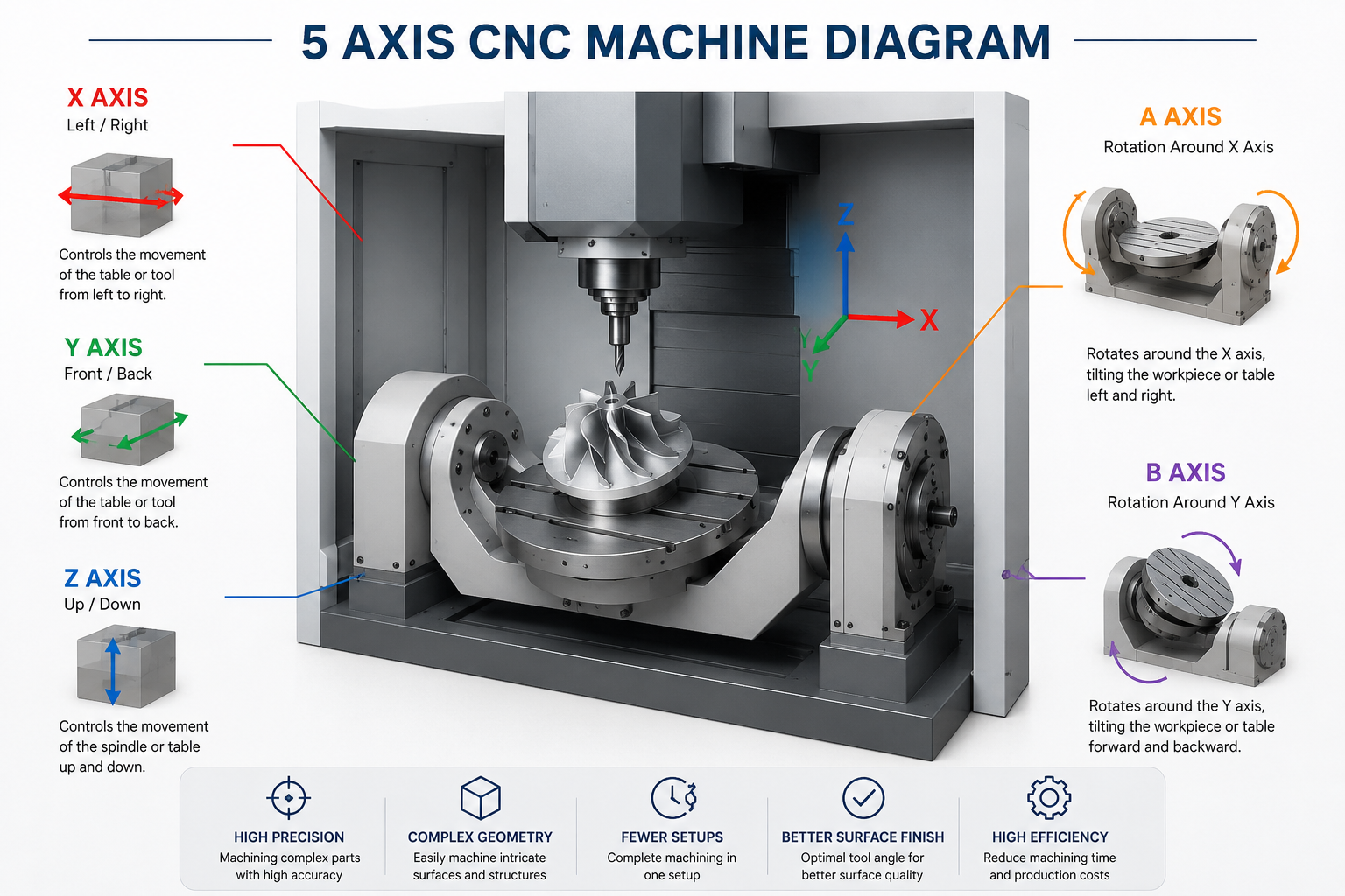
In this context, X, Y, and Z are linear motion axes, while A and B are rotational motion axes.
It is precisely these two additional rotational axes that enable five-axis machine tools to machine complex parts in a single setup.
What is the X-axis?
The X-axis is one of the most basic axes of motion in a CNC machine tool, responsible for movement from left to right.
In most vertical machining centers, the X-axis controls the movement of the worktable or cutting tool horizontally from left to right. During machining, the X-axis is typically used to control positional changes along the length of the part.
Simply put:
Left ← → Right
The X-axis and Y-axis together determine the tool’s position within the plane.
What is the Y-axis?
The Y-axis is responsible for movement in the front-to-back direction.
It controls the movement of the tool or worktable across the width of the workpiece.
This can be understood as:
Front ← → Back
When the X-axis and Y-axis move simultaneously, the machine tool can perform various contouring, slotting, and milling operations on a plane.
What is the Z-axis?
The Z-axis controls movement in the vertical direction.
It controls the tool’s approach to or retreat from the workpiece and determines the cutting depth.
This can be understood as:
Up ↑ ↓ Down
Operations such as drilling, slotting, and cavity machining all rely on precise Z-axis control.
The X, Y, and Z axes together form the foundation of traditional three-axis CNC machine tools.
What is the A-axis?
The A-axis is a motion axis that rotates around the X-axis.
Unlike the linear motion of the X, Y, and Z axes, the A-axis changes the machining angle by rotating the workpiece or the rotary table.
With the A-axis, a machine tool can more easily machine:
- Angled holes
- Side grooves
- Multi-angle planes
- Circumferentially distributed features
Without the A-axis, these features often require re-clamping the workpiece to complete.
What is the B-axis?
The B-axis is a motion axis that rotates around the Y-axis.
The B-axis allows the workpiece or tool to tilt in different directions, enabling more complex machining paths.
When the B-axis is used in conjunction with the A-axis, the tool can approach the workpiece surface from virtually any angle.
This is also the key reason why five-axis CNC machine tools are capable of machining complex and free-form surfaces.
Do five-axis machine tools always have A and B axes?
Not necessarily.
Many people believe that a five-axis CNC machine tool must include:
X + Y + Z + A + B
In reality, different machine tool configurations may use different combinations of rotary axes.
For example:
- A + B
- A + C
- B + C
Where:
- A-axis rotates around the X-axis
- B-axis rotates around the Y-axis
- C-axis rotates around the Z-axis
Although the configurations differ, their purpose is the same: to allow the cutting tool to access the workpiece from more angles, thereby reducing the number of setups and improving machining efficiency.
Why Are Two Additional Rotation Axes Needed?
Many people ask:
If a three-axis CNC machine already has three directions of motion—X, Y, and Z—why are the A and B axes necessary?
The answer is simple:
To allow the cutting tool to approach the workpiece from more angles.
For simple parts, three-axis machining is usually sufficient. However, as part geometries become increasingly complex, traditional three-axis machines encounter many limitations.
For example:
- Angled holes
- Deep cavities
- Complex surfaces
- Multi-faceted machining features
- Impeller blade structures
These features often cannot be machined from a single direction.
When using a three-axis machine, operators typically need to:
- Remove the workpiece multiple times
- Re-clamp and reposition it
- Re-calibrate the coordinates
This not only increases machining time but also leads to cumulative errors.
By adding a rotational axis, a five-axis machine tool can automatically adjust the angle of the workpiece or the tool, ensuring the tool always cuts from the optimal direction, thereby improving machining efficiency and precision.
Conclusion
A five-axis CNC machine tool consists of three linear axes (X, Y, Z) and two rotary axes (A, B, or C). Compared to traditional three-axis machine tools, the additional rotary axes allow the cutting tool to approach the workpiece from more angles, enabling the machining of complex parts in a single setup.
For simple parts, three- or four-axis machining is often sufficient; however, for parts with complex surfaces, multi-angle features, and high-precision requirements, five-axis CNC machining is typically a more efficient and precise solution.
Frequently Asked Questions
5-axis machining is recommended for parts with complex curves, deep cavities, multiple angled features, or tight positional tolerances. If your component requires machining from several directions or minimizing setup changes, 5-axis machining is often the most efficient solution.
In many cases, yes. Because a 5-axis machine can complete more features in a single setup, it reduces repositioning errors and improves dimensional consistency. This makes it particularly suitable for aerospace, medical, and high-precision industrial components.
Absolutely. Our engineering team can review your CAD files or drawings and recommend the most suitable machining process based on part geometry, tolerance requirements, material selection, and production volume. In some cases, a 3-axis or 4-axis process may provide a more cost-effective solution.
We machine a wide range of materials, including aluminum, stainless steel, titanium, tool steel, brass, copper, PEEK, Nylon, Delrin, and other engineering plastics. Material recommendations can also be provided based on your application and performance requirements.
Yes. We can provide dimensional inspection reports, CMM reports, first article inspection (FAI) reports, and material certificates upon request. All critical dimensions can be verified before shipment.
The easiest way is to send us your drawings for a free engineering review. Our team will evaluate manufacturability, recommend the optimal machining strategy, identify potential cost-saving opportunities, and provide a detailed quotation based on your project requirements.



