
A 3-axis CNC machine is one of the most common types of CNC machining equipment. It uses computer control to move the cutting tool or worktable along the X, Y, and Z axes, thereby performing operations such as drilling, milling, slotting, tapping, and contour machining.
What Are the X, Y, and Z Axes on a CNC Machine?
A 3-axis CNC machine is called “3-axis” because it can move in three different directions.
X Axis
The X-axis is responsible for movement from side to side.
In a vertical machining center, the table typically moves left or right to control the machining position along the length of the part.
Y Axis
The Y-axis is responsible for movement from front to back.
Through movement along the Y-axis, the tool can cover the machining area across the width of the part, enabling the cutting of two-dimensional contours and complex planar features.
Z-Axis
The Z-axis is responsible for vertical movement.
It determines the cutting depth of the tool and is a critical axis for performing drilling, milling, and cavity machining.
When the three coordinate axes work together, the tool can machine along a preset path in three-dimensional space.

How Does 3-Axis CNC Machining Work?
A three-axis CNC machine tool uses computer programs to control the movement of the cutting tool and workpiece along the three linear coordinate axes (X, Y, and Z), thereby performing material cutting and part machining. The entire machining process begins with a digital model and proceeds through multiple stages, including program generation, machine setup, automated machining, and quality inspection, ultimately producing parts that meet design specifications.
The following is a typical 3-axis CNC machining process.
Step 1: Create a CAD Design Model
The machining process begins with part design. Engineers use CAD (Computer-Aided Design) software to create two-dimensional drawings or three-dimensional models of the part, defining critical dimensions, tolerances, and structural features.
This digital model serves as the part’s “blueprint” and determines all subsequent machining steps.
Step 2: Generate G-Code Programs
Once the design is complete, the CAD model is imported into CAM (Computer-Aided Manufacturing) software.
The CAM software automatically calculates toolpaths based on the part’s geometry, tool specifications, and machining strategies, and generates G-code. G-code is a control language recognized by CNC machines, containing information such as spindle speed, feed rate, cutting depth, tool changes, and movement coordinates.
Step 3: Import the Program and Verify Parameters
The generated G-code is transferred to the CNC machine’s control system.
Before actual machining begins, technicians verify the program content, machining sequence, tool selection, and critical parameters to ensure the program can be executed safely and accurately.
Step 4: Workpiece Clamping and Tool Setting
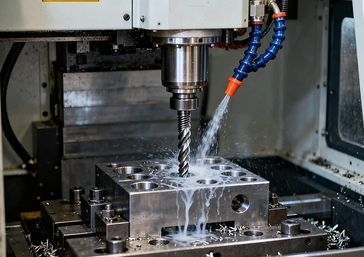
Before machining begins, the raw material must be securely clamped to the machine table or a specialized fixture.
The cutting tools are then installed, and a workpiece coordinate system is established through tool setting and coordinate calibration. Proper clamping and tool setting are critical for ensuring machining accuracy and stability.
(Suitable for inserting here: a photo of the machining site showing the workpiece clamped on the CNC table)
Step 5: Executing the Machining Program
Once setup is complete, the machine tool begins automatic operation.
The control system uses G-code instructions to guide the tool and workpiece along the X, Y, and Z axes. Through processes such as milling, drilling, tapping, boring, and slotting, excess material is progressively removed to ultimately form the desired part shape.
Throughout the process, the machine tool continuously performs high-precision machining along the preset path.
Step 6: Inspection and Post-Processing
Once machining is complete, the part undergoes dimensional and quality inspection to verify compliance with the drawing specifications.
Depending on product requirements, post-processing steps such as deburring, polishing, anodizing, electroplating, and sandblasting may be performed to enhance the part’s surface finish, corrosion resistance, and performance.
After passing inspection, the part proceeds to the packaging and delivery stage.
What Can a 3 Axis CNC Machine Make?
Although three-axis CNC machines cannot machine complex surfaces in a single setup like five-axis machines can, they are still capable of producing a wide range of industrial parts. For parts that can be machined from a single direction or with only a few repositioning operations, three-axis CNC is often the most cost-effective option.
The following are typical applications of three-axis CNC machine tools in various industries:
Automotive Industry
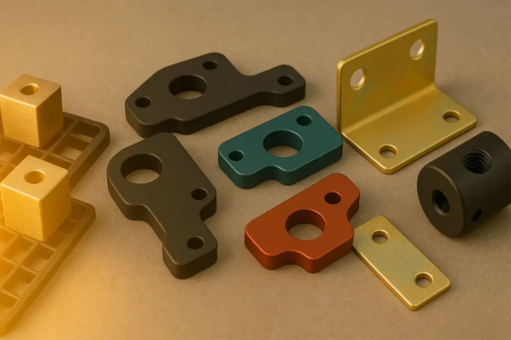
In the automotive industry, 3-axis CNC machining is commonly used to produce brackets, flanges, mounting plates, transmission housing components, and various aluminum alloy structural parts. For standard mechanical parts requiring high-volume production, 3-axis machining offers a balance of efficiency and cost control.
Electronics Industry
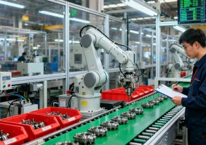
The electronics industry extensively uses 3-axis CNC to manufacture heat sinks, controller housings, instrument panels, sensor enclosures, and various precision structural components. Aluminum alloys and engineering plastics are the most common materials processed.
Aerospace Industry
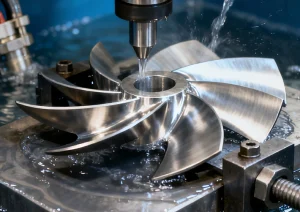
Although complex aerospace parts typically require 5-axis machining, mounting brackets, equipment panels, connecting structural components, and auxiliary assemblies in many aerospace projects are still predominantly manufactured using 3-axis CNC.
Medical Industry
Mounting assemblies, structural components for diagnostic equipment, and certain surgical instrument parts in medical devices demand high dimensional accuracy and surface quality, and 3-axis CNC machining delivers consistent and reliable results.
Prototyping and Product Development
During the product development phase, 3-axis CNC is frequently used for rapid manufacturing of functional prototypes and engineering validation parts. Compared to mold-based production, it enables faster design validation and reduces development costs.
Mold and Tooling Industry
Mold bases, fixtures, gauges, and various tooling jigs are among the most common applications for 3-axis CNC. For parts requiring extensive flat surface machining and hole patterns, 3-axis machines are typically the most cost-effective choice.

Common Types of Three-Axis CNC Machines
Although all three-axis CNC machines move along the three linear coordinate axes (X, Y, and Z), there are significant differences in their structural design, machining capabilities, and applications. Depending on the workpiece dimensions, material type, machining accuracy, and production requirements, manufacturers typically select the most suitable equipment to complete the machining task.
Listed below are some of the most common types of three-axis CNC machines used in manufacturing, along with their typical applications.
| Machine Type | Key Features | Typical Applications | Advantages | Limitations |
|---|---|---|---|---|
| Vertical Machining Center (VMC) | Vertical spindle, automatic tool changer, high precision | Milling, drilling, tapping, precision parts | Versatile, accurate, highly automated | Limited access to multiple sides of complex parts |
| Bed-Type Milling Machine | Rigid machine structure designed for larger workpieces | Large plates, molds, machine components | High rigidity, stable cutting performance | Slower setup and lower automation |
| CNC Router | High-speed spindle with large work area | Woodworking, plastics, composites | Fast machining and lower operating costs | Not suitable for heavy metal cutting |
| Gantry CNC Machine | Bridge-style structure for large workpieces | Aerospace panels, machine bases, large aluminum plates | Large machining capacity and excellent stability | Higher machine investment cost |
Pros Of 3-Axis CNC Machining
High Precision
Modern 3-axis CNC machines can achieve tight tolerances and consistent part quality.
Excellent Repeatability
Ideal for batch production where identical parts must be produced repeatedly.
Lower Machining Costs
Lower machine investment, simpler programming, and reduced setup costs compared with 4-axis and 5-axis machining.
Easy Programming and Operation
Toolpaths are simpler, making production planning and operator training easier.
Wide Range of Applications
Suitable for brackets, housings, fixtures, plates, and many standard industrial components.
Cons Of 3-Axis CNC Machining
Multiple Setups Required
Parts often need to be re-clamped and repositioned to machine multiple sides.
Limited Access to Complex Features
Deep cavities, undercuts, and intricate geometries can be difficult or impossible to machine efficiently.
Longer Machining Time for Complex Parts
Multiple setups increase production time and reduce efficiency.
Lower Accuracy Across Multiple Faces
Repositioning introduces the possibility of cumulative alignment errors.
How We Help Customers with 3-Axis CNC Machining Projects
At YUANYI, 3-axis CNC machining remains one of the most commonly used machining methods in our workshop. We produce large quantities of parts such as mounting brackets, equipment base plates, enclosures, fixtures, and various mechanical structural components on a daily basis.
Before a project begins, our engineering team evaluates the most suitable machining solution based on the part’s geometry, dimensional requirements, and budget. For parts suitable for 3-axis machining, we typically prioritize 3-axis CNC to help customers reduce machining costs while ensuring consistent machining quality.
If you are evaluating whether your part is suitable for 3-axis CNC machining, send us your drawings. Our engineers will review the part structure and provide professional advice with a fast quotation.
Get a Fast CNC Machining QuoteFAQ
For most precision-machined parts, we can achieve tolerances of ±0.01 mm. For critical features and well-controlled machining conditions, tolerances up to ±0.005 mm are possible.
We machine a wide range of materials, including aluminum, stainless steel, carbon steel, brass, copper, titanium, and engineering plastics such as POM, Nylon, PEEK, and Acrylic.
Yes. We support everything from single prototype parts to full production runs. There is no minimum order quantity (MOQ).
In most cases, we provide quotations within 24 hours after receiving your drawings and project requirements.
Yes. We can provide dimensional inspection reports, first article inspection (FAI) reports, material certificates, and other quality documentation upon request.



