

In mechanical design, welding, and CNC machining, a bevel is a common design feature. Many people confuse it with a chamfer or a fillet, but in fact, a bevel affects not only the appearance of a part but also assembly, welding, and manufacturing processes.
From simple bevels on shaft ends to complex welding grooves, bevels are widely used in a variety of engineering parts. This article will explain what a bevel is, its common types, engineering applications, and manufacturing methods in CNC machining.
What is a Bevel?
A bevel refers to an inclined surface machined between two intersecting surfaces.
The most common application involves cutting an original 90° right angle into a bevel at a specific angle, such as 30°, 45°, or 60°. Compared to maintaining a sharp right angle, a bevel removes some material, creating a smooth transition at the edge.
From a geometric perspective, a bevel is not complicated; it is essentially an inclined surface. However, in the field of engineering, this seemingly simple feature serves many important functions.
Therefore, a bevel is not merely a method of edge finishing, but rather a design feature with a specific engineering purpose.
What Is a Beveled Edge?
A bevel edge refers to an edge that has been machined with a bevel.
If a part maintains a perfect 90° right angle, its edges are typically quite sharp. However, when engineers remove material from the edge at a specific angle, this creates what is known as a beveled edge.
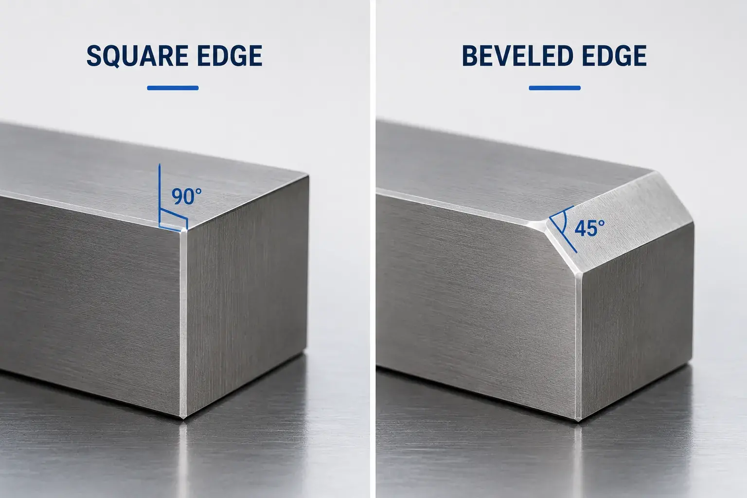
In actual products, beveled edges are virtually ubiquitous.
For example, locating pins, bushings, flanges, connecting plates, and various CNC-machined parts in mechanical equipment often feature small bevels on their edges. For these parts, bevels not only reduce the risk of scratches from sharp edges but also facilitate smoother assembly.
In consumer electronics, bevel edges are also frequently used to enhance the product’s perceived quality. For example, beveled designs on smartphone bezels, laptop casings, and instrument panels all make the products appear more refined.
Therefore, the value of a beveled edge is often reflected not only in its appearance but also in its functionality and manufacturing efficiency.
Common Types of Bevels
Although all bevels are sloped structures, their forms vary significantly depending on application requirements.
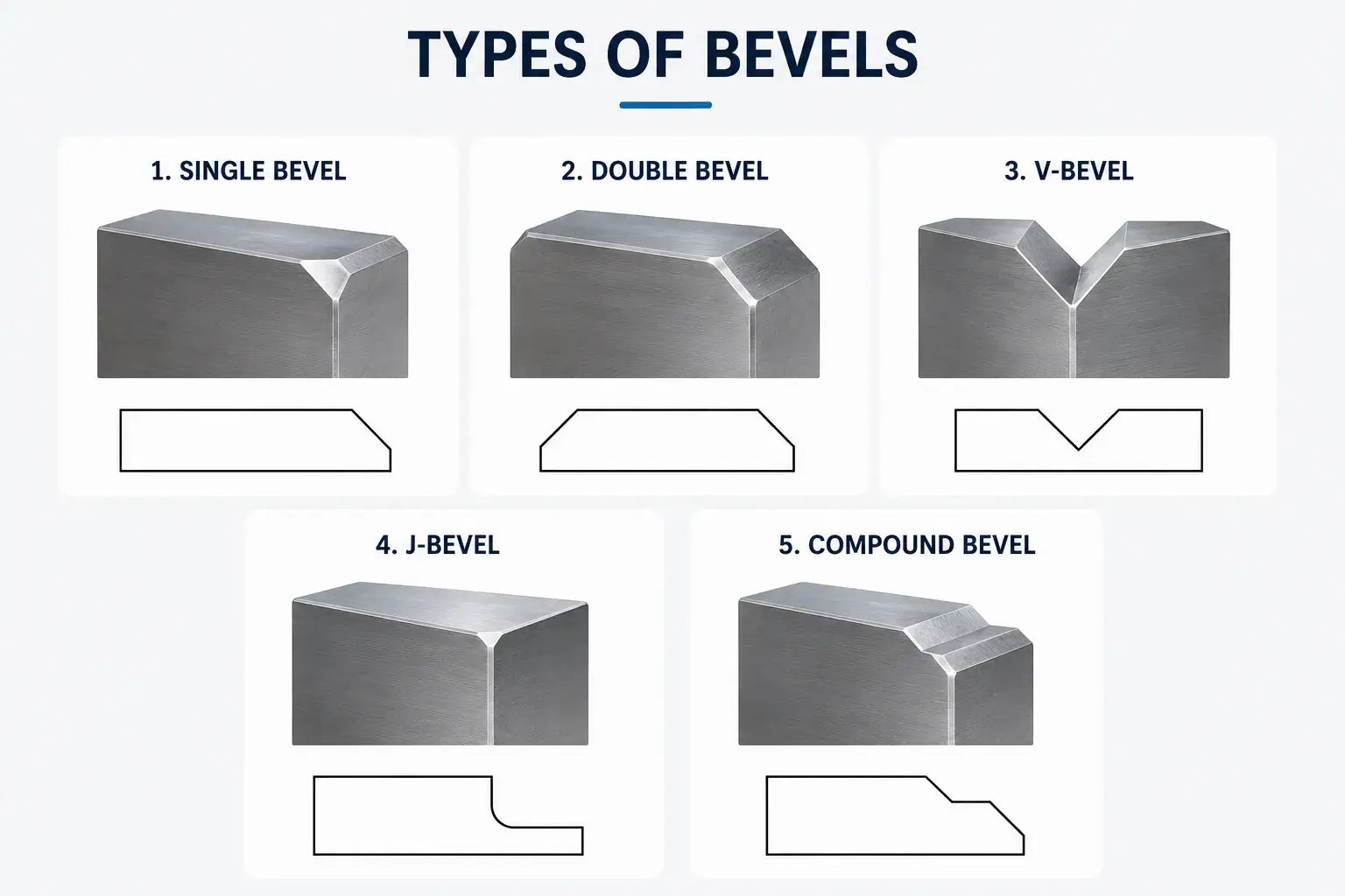
Single Bevel
The single bevel is the simplest and most common type.
As the name suggests, it involves machining a bevel on only one side of the edge, while the other side retains its original shape. This structure is widely used in general mechanical parts, assembly guide structures, and simple welding grooves.
Due to its simplicity and lower cost, it is the most common type in CNC-machined parts.
Double Bevel
A Double Bevel involves machining bevels on both sides of the edge simultaneously.
Compared to a Single Bevel, a Double Bevel creates a more symmetrical structure, making it more common in thick-plate welding and high-strength joints.
For some large structural components, a Double Bevel can also improve the distribution of welding stresses and enhance the overall quality of the joint.
V-Bevel
The V-Bevel is one of the most common groove types in the welding industry.
When two pieces of material are butt-joined, the bevels on both sides form a V-shaped groove. During welding, filler material can fully penetrate the groove, resulting in better weld penetration.
V-grooves are widely used in steel structures, pressure vessels, and heavy equipment manufacturing.
J-Bevel (J-Groove)
Unlike the V-Bevel, one side of the J-Bevel features a rounded transition.
This design reduces the amount of filler material required while ensuring weld quality, making it a common choice for thick-walled pressure vessels, piping systems, and high-value welded structural components.
However, because J-Bevels are more difficult to machine, their manufacturing costs are typically higher than those of standard V-Bevels.
Compound Bevel
Compound bevels are commonly found in the aerospace, medical device, and precision machinery industries.
This type of bevel typically consists of multiple bevels at different angles and is sometimes combined with curved transitions.
Compound bevels can meet specific requirements for assembly, fluid flow, or structural optimization, but they also place higher demands on CNC programming and machining capabilities.
How to Measure a Bevel?
For standard parts, engineers typically need to verify that the dimensions and angle of the bevel meet the drawing specifications.
The most common notation is:
2 × 45°
This indicates that a bevel with a width of 2 mm and an angle of 45° must be machined.
Depending on the required precision, common bevel measurement tools include:
- Bevel Protractor: Suitable for quickly measuring bevel angles, it is one of the most common inspection tools in the workshop.
- Digital Angle Gauge: Displays the measured angle directly; it is easy to operate and suitable for on-site inspection.
- Universal Bevel Protractor: Offers high measurement accuracy and is commonly used in machining and quality inspection.
- Caliper: Measures the width of the bevel and, in conjunction with drawings, determines whether the angle meets specifications.
Coordinate Measuring - Machine (CMM): Suitable for high-precision part inspection. By collecting data from multiple measurement points, a CMM can accurately calculate the bevel’s actual angle, dimensions, and positional tolerances, and generate a comprehensive inspection report.
For general CNC-machined parts, a bevel gauge or digital angle gauge is usually sufficient to meet inspection requirements; however, for aerospace, medical devices, and high-precision automated parts, manufacturers prefer to use a CMM for final verification to ensure that the bevel dimensions comply with drawing specifications.
What is the difference between a bevel, a chamfer, and a fillet?
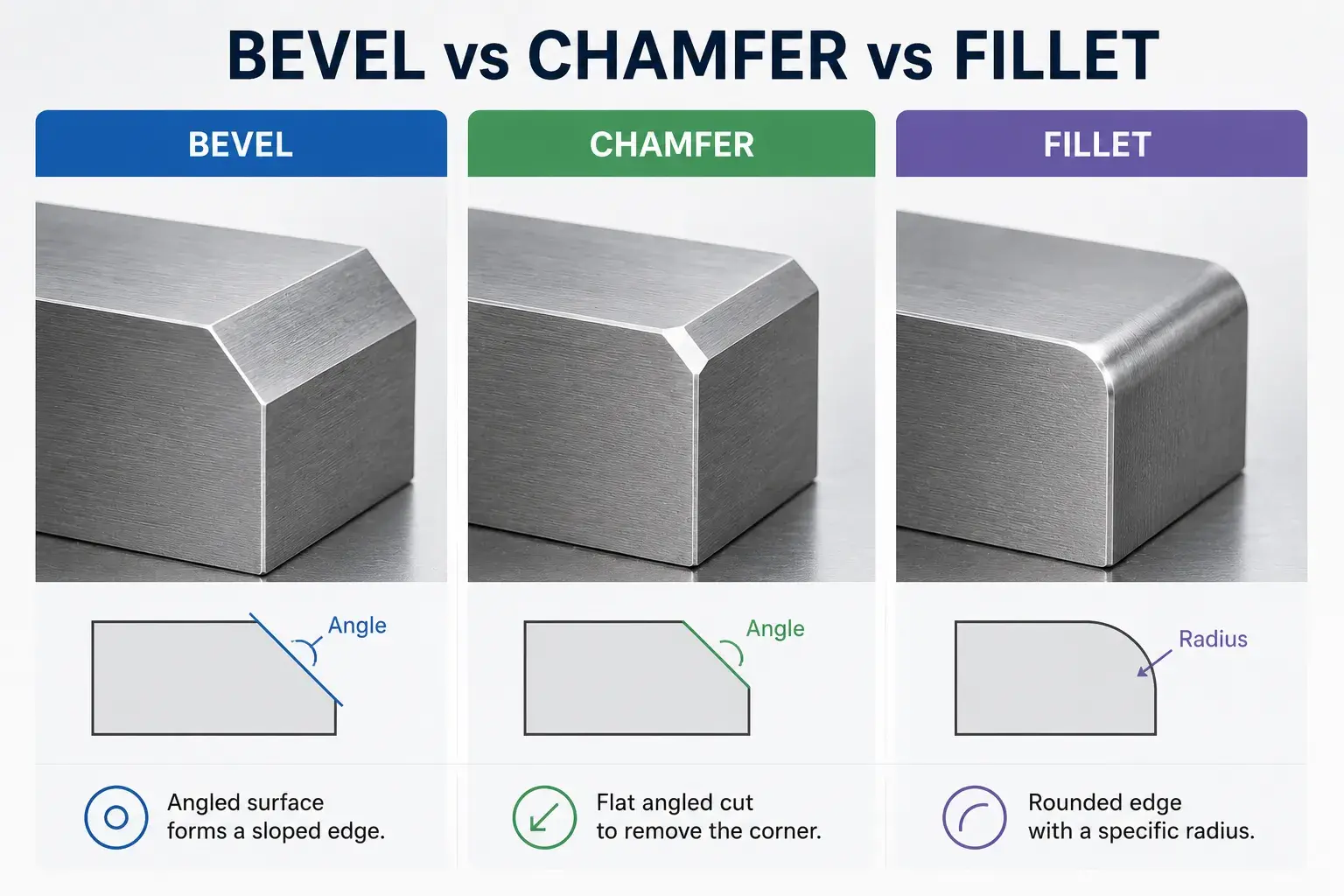
In mechanical design and CNC machining, bevels, chamfers, and fillets are all types of edge treatments, which is why they are often confused. Although they all appear to alter the shape of a part’s edges, their design purposes and applications differ.
Here are the main differences between the three:
| Feature | Bevel | Chamfer | Fillet |
|---|---|---|---|
| Shape | Angled Surface | Small Angled Surface | Rounded Edge |
| Typical Angle | Any Angle | Usually 45° | No Fixed Angle |
| Main Purpose | Welding, Assembly, Functional Design | Remove Sharp Edges, Ease Assembly | Reduce Stress Concentration |
| Common Drawing Callout | 2×30°, 3×45° | C0.5, C1 | R1, R2 |
| Machining Method | Milling, Turning, Grinding | Chamfer Mill, End Mill, Turning Tool | Ball Nose End Mill, Radius Cutter |
Why Are Bevels Used in Engineering?
Although a bevel may look like a simple angled edge, it often serves an important engineering purpose. Depending on the application, a bevel can improve assembly, support welding, protect part edges, enhance safety, and improve product appearance.
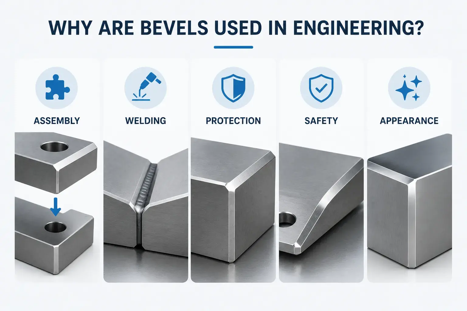
Improve Assembly
Bevels help guide components into position during assembly. They are commonly used on shafts, pins, bushings, and mating parts to reduce interference and make installation easier.
Prepare for Welding
In welding applications, bevels create space for weld penetration. Common bevel types such as V-bevels and J-bevels help improve weld strength and joint quality, especially on thick materials.
Protect Part Edges
Sharp corners are more likely to chip or become damaged during handling and transportation. Adding a bevel helps protect the edge and improve part durability.
Improve Safety
Bevels remove sharp edges that could cause injuries during handling, assembly, or maintenance. This is why many engineering drawings specify edge-breaking requirements.
Enhance Appearance
A clean bevel edge can make a product look more refined and professional. Bevels are commonly used on consumer products, medical devices, and high-end industrial equipment for aesthetic purposes.
How Is a Bevel Machined?
A bevel may appear to be a simple slanted surface, but the actual machining method varies depending on the part’s structure, material type, angle requirements, and precision requirements.
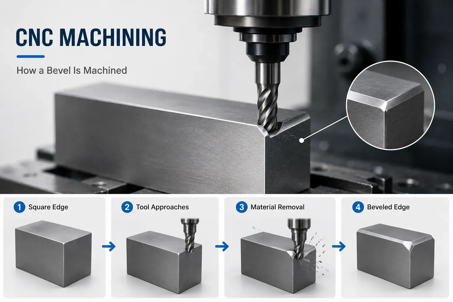
For most CNC-machined parts, bevels are typically created through milling or turning. However, bevels on complex curved surfaces may require four-axis or five-axis machining equipment.
CNC Milling
CNC milling is one of the most common methods for manufacturing bevels.
For flat plates, brackets, housings, and various parts with edged structures, chamfering cutters, angle milling cutters, or end mills are typically used to cut along the edges, thereby forming the desired bevel.
This method is highly efficient and cost-effective, and is suitable for most materials, including aluminum alloys, stainless steel, steel, and engineering plastics.
CNC Turning
For shaft-type parts, bushings, pins, and various cylindrical parts, bevels are typically created using a CNC lathe.
The most common application is machining a small bevel at the end of a shaft to remove sharp edges and improve assembly performance. This helps the part slide more smoothly into the mating hole while reducing the risk of edge damage.
4-Axis CNC Machining
When multiple sides of a part require beveling, 4-axis machining typically improves processing efficiency.
By coordinating the rotation axis with the cutting action, the machine can complete beveling in multiple directions during a single setup, thereby reducing errors caused by repeated setups and improving the consistency of bevels at different locations.
Five-Axis CNC Machining
For bevels on parts used in aerospace, medical devices, and those with complex curved surfaces, five-axis CNC machining is typically required.
Five-axis machines can adjust the tool angle in real time based on the part’s geometry, ensuring the tool always maintains the optimal cutting orientation. As a result, even bevels located in deep pockets, on curved surfaces, or in hard-to-reach areas can achieve high dimensional accuracy and surface quality.
What Factors Affect the Difficulty of Machining Bevels?
Although bevels are a common machining feature, their machining difficulty varies.
The following factors all influence machining costs and manufacturing complexity:
- The size of the bevel
- The required bevel angle
- Type of part material
- Accessibility of the machining location
- Tolerance requirements
- Surface roughness requirements
Generally speaking, standard 45° bevels on open edges are the easiest to machine, while bevels located on complex curved surfaces, inside deep cavities, or with special angle requirements often require more machining time and more advanced equipment.
How Does YUANYI Machine High-Precision Bevel Parts?
At YUANYI, we have extensive experience in CNC machining and are capable of machining a wide range of standard and complex bevel features, including standard bevels, weld grooves, and multi-angle structures on complex curved surfaces.
Leveraging our 3-axis, 4-axis, and 5-axis CNC machining capabilities, we achieve machining accuracies as high as ±0.005 mm and support a wide range of materials, including aluminum alloys, stainless steel, titanium alloys, copper alloys, and engineering plastics.
For bevel features with strict dimensional requirements, we also provide CMM inspection and comprehensive dimensional reports to ensure parts meet drawing specifications and quality standards.
Need Precision Beveled Parts?
Send us your CAD file or drawing, and our engineering team will review your bevel features, machining requirements, and tolerance needs to provide a fast quotation.
Get a Free QuoteConclusion
A bevel is a common engineering feature in mechanical design and manufacturing, widely used in applications such as assembly, welding, edge protection, and aesthetic optimization. Although it may appear to be a simple sloped surface, a well-designed bevel can enhance product performance, improve manufacturing processes, and elevate the overall user experience.
Frequently Asked Questions
No. A chamfer is typically a small angled edge used to remove sharp corners or assist assembly, while a bevel can be larger and often serves a functional purpose such as welding preparation, alignment, or structural design.
The most common bevel angle in machining is 45°. However, 30°, 37.5°, and 60° bevels are also widely used depending on the application, especially in welding and assembly features.
Bevels create additional space for weld penetration and filler material. This helps produce stronger weld joints and improves weld quality, particularly when joining thick materials.
Yes. Bevels can be machined on most engineering materials, including aluminum, stainless steel, carbon steel, titanium, brass, copper, and engineering plastics. The machining method may vary depending on the material properties.
A bevel should typically be defined by its size and angle, such as 2 × 45°. If the bevel is critical to assembly, sealing, or welding performance, the drawing should also specify any required tolerances or surface finish requirements.
Yes. For critical bevel features, we can perform dimensional verification using precision measuring tools or CMM inspection and provide inspection reports upon request.
Yes. If a bevel is difficult to machine, unnecessarily tight, or increases manufacturing cost, our engineers can provide DFM (Design for Manufacturability) suggestions to improve machinability while maintaining the part’s function.
We regularly machine bevels on aluminum, stainless steel, titanium, brass, copper, engineering plastics, and many other materials used in aerospace, medical, automation, and industrial applications.



