
How to Design Parts for 5 Axis CNC Machining: Practical DFM Tips

Engineer reviewing a CAD model for 5-axis CNC machining design and DFM analysis

Five-axis machining does indeed allow access to parts from multiple angles and reduces the number of setups. However, the design of the part itself still directly affects machining difficulty, machining cost, surface finish, and lead time.

Some parts may appear complex, but if designed properly, they can actually be machined relatively smoothly. Other parts may not look particularly complex, yet poor tool access, excessively small internal corners, overly deep cavities, or overly tight tolerances can lead to significantly increased machining time and costs.

Therefore, good CNC part design is not simply about making the part more complex, but about making it easier to machine reliably, accurately, and cost-effectively.

This article will discuss, from a DFM perspective, how to design parts that are better suited for five-axis machining, as well as which design issues tend to increase machining costs.

Why Design Matters in 5 Axis CNC Machining

In 5-axis CNC machining, design is crucial.

While 5-axis machines allow the cutting tool to approach the workpiece from more angles, this does not mean that any part can be machined cost-effectively. If the part design does not take into account tool clearance, clamping methods, and machining sequence, many problems will still arise during actual production.

For example, consider a deep-cavity aluminum alloy housing: if the cavity is very deep and the opening is very narrow, the cutting tool must extend a long distance. The longer the tool, the more prone it is to vibration, and the machining speed must be reduced. This not only affects the surface finish but also increases cycle time.

A small adjustment during the design phase can often minimize many subsequent machining issues. For example, appropriately increasing the internal corner radius, relaxing tolerances on non-critical dimensions, or providing better access for the cutting tool can all lead to more stable machining and a more reasonable quote.

In other words, five-axis machining is not a magic bullet. It can solve many complex machining problems, but only if the part design itself is suitable for manufacturing.

What Types of Parts Are Suitable for 5-Axis Machining?

Not all parts require 5-axis machining.

If a part consists only of simple flat surfaces, standard hole patterns, or a small number of side-face machining operations, 3-axis or 4-axis machining may be sufficient. 5-axis machining is better suited for parts with complex geometries, multiple machining angles, difficult-to-clamp features, or those requiring high precision consistency.

Common parts suitable for 5-axis machining include:

  • Structural components with complex geometries
  • Deep-cavity aluminum alloy housings
  • Parts with multiple and angled holes
  • Aerospace parts
  • Medical device parts
  • Robotic structural components
  • Mold cavities
  • Precision automation equipment parts

These parts often share a common characteristic: if machined using conventional 3-axis methods, they would require multiple setups or it would be difficult to access critical areas from the appropriate angles.

With five-axis machining, the cutting tool can approach the workpiece from different directions, making “one-setup machining” possible. This reduces the need for repeated positioning and improves positional accuracy between different machined surfaces.

However, whether five-axis machining is truly necessary depends on the part’s structure. The most sensible approach is to select the machining process based on the specific challenges of the part, rather than automatically resorting to five-axis machining simply because the part has a complex structure.

Key CNC Part Design Tips for 5-Axis Parts

Keep Tool Access in Mind

When designing 5-axis parts, the first consideration should be tool access. Many machining issues aren’t caused by the machine’s limitations, but rather because the tool simply cannot reach the workpiece. Even though 5-axis machines can adjust their angles, tool and toolholder interference may still occur if the machining area is blocked by high walls, deep grooves, or narrow spaces.

For deep cavities, side holes, inclined surfaces, and undercuts, make sure to leave sufficient space for the tool during the design process. Adequate tool clearance reduces the risk of collisions and ensures a more stable machining process.
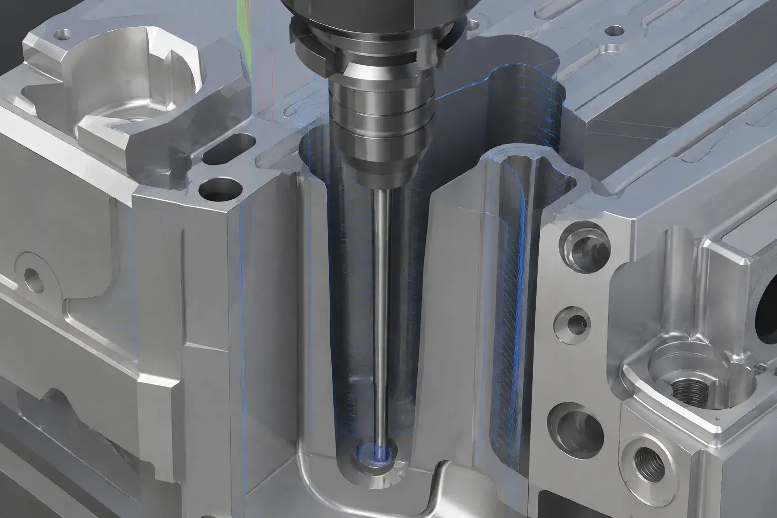
Tool access and tool clearance for 5-axis CNC machining part design

Avoid Deep and Narrow Cavities When Possible

Deep and narrow cavities significantly increase machining difficulty. The deeper the cavity, the longer the tool protrudes, resulting in reduced rigidity and increased susceptibility to vibration during machining.

If functionality permits, consider widening the cavity opening to reduce unnecessary deep and narrow structures. This not only shortens cycle time but also improves surface quality and reduces tooling costs.
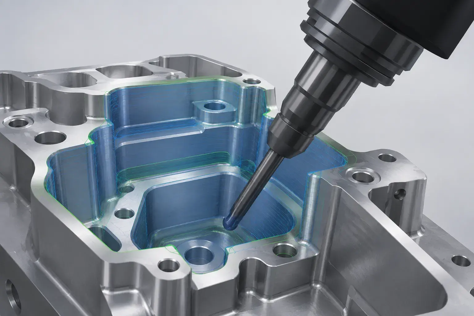
Deep narrow cavity design increasing tool reach in 5-axis CNC machining

Use Proper Internal Corner Radius

Even with multi-axis machining, the tool itself remains circular, so it is difficult to machine internal corners into true sharp angles. If the internal corner radius is too small, engineers must use smaller tools, which reduces machining efficiency.

Provided it does not affect assembly or functionality, it is recommended to use a larger internal corner radius whenever possible. This reduces tool changes, ensures smoother cutting, and shortens machining time.
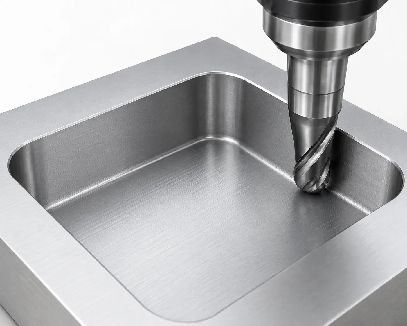
Proper internal corner radius design for CNC machined aluminum parts

Avoid Unnecessary Tight Tolerances

The tighter the tolerances, the higher the machining and inspection costs typically are. For many parts, only assembly holes, mating surfaces, or critical locating surfaces require high precision; not all external surfaces need strict tolerances.

A better practice is to distinguish between critical dimensions and general dimensions. Critical locations can retain tighter tolerances, while non-critical areas can use reasonable general tolerances, making the costs of precision CNC machining more manageable.

Keep Wall Thickness Reasonable

Thin walls are prone to vibration and deformation during machining. While five-axis machining can reduce the number of clamping operations, it cannot completely eliminate material deformation.

When designing thin-walled parts, strike a balance between weight, strength, and machining stability. If the wall thickness is too thin, it is recommended to have a machining engineer evaluate the design in advance to avoid issues such as deformation, dimensional instability, or surface quality problems later on.

Design Features for One-Setup Machining

One-Setup Machining is a key advantage of five-axis machining. For parts with holes, slots, chamfers, or complex features on multiple sides, five-axis machining can reduce the need for flipping the part and repeated setups.

By considering multi-sided machining early in the design phase, you can better leverage the benefits of five-axis machining. For example, positioning critical holes and mating surfaces in locations suitable for single-setup machining can improve positional accuracy and shorten lead times.
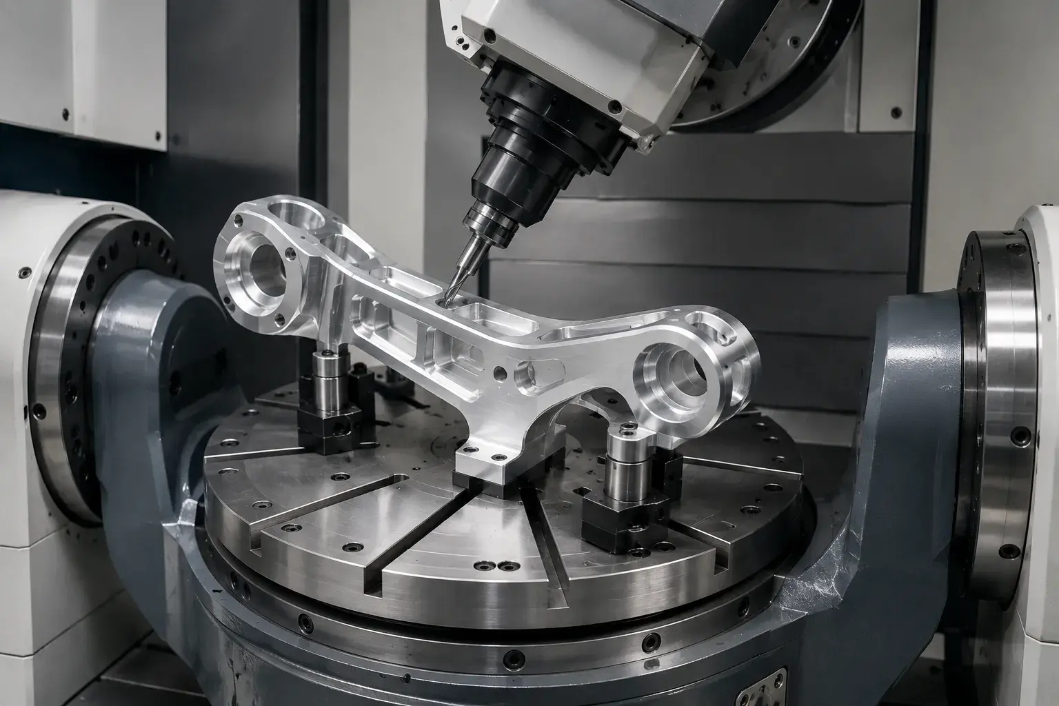
One-setup 5-axis CNC machining for multi-sided aluminum part features

Common Design Mistakes That Increase Machining Costs

In many cases, the high cost of five-axis machining is not necessarily due to the complexity of the part, but rather to certain design issues that are easily overlooked.

Common issues include:

  • Cavities that are too deep or too narrow
  • Internal fillet radii that are too small
  • Tight tolerances specified for all features
  • Excessive use of thin-walled structures
  • Failure to account for tool access
  • Complex angular features with no practical functional purpose
  • Failure to allow clearance for fixtures and tool holders
  • Surfaces that are overly complex but offer little functional benefit

These issues all make machining slower and more complex, and are more likely to drive up costs.

When Multi-Axis Machining Is Not Necessary

Multi-axis machining is powerful, but it isn’t necessary for every part.

If a part has a relatively simple structure—such as flat surfaces, standard holes, shallow grooves, or only a few side features—three-axis or four-axis machining may already meet the requirements. In such cases, forcing the use of five-axis machining may not necessarily yield significant benefits.

Some customers assume that 5-axis machining is inherently more precise and advanced. In reality, the quality of a part is influenced not only by the number of machine axes but also by the machining strategy, clamping method, tool selection, and quality inspection.

If a part can consistently meet drawing specifications using 3-axis machining, then choosing 3-axis machining may be more cost-effective. If a part requires multi-surface machining but lacks complex curved surfaces, 3+2-axis machining may also be more suitable than simultaneous 5-axis machining.

A good supplier will not recommend the most complex process right from the start, but will instead select the most reasonable machining strategy based on the part’s geometry and project requirements.

How DFM Review Helps Improve Your Part Design

The purpose of a DFM review is to identify potential design issues that could affect manufacturing well in advance of formal quoting or machining.
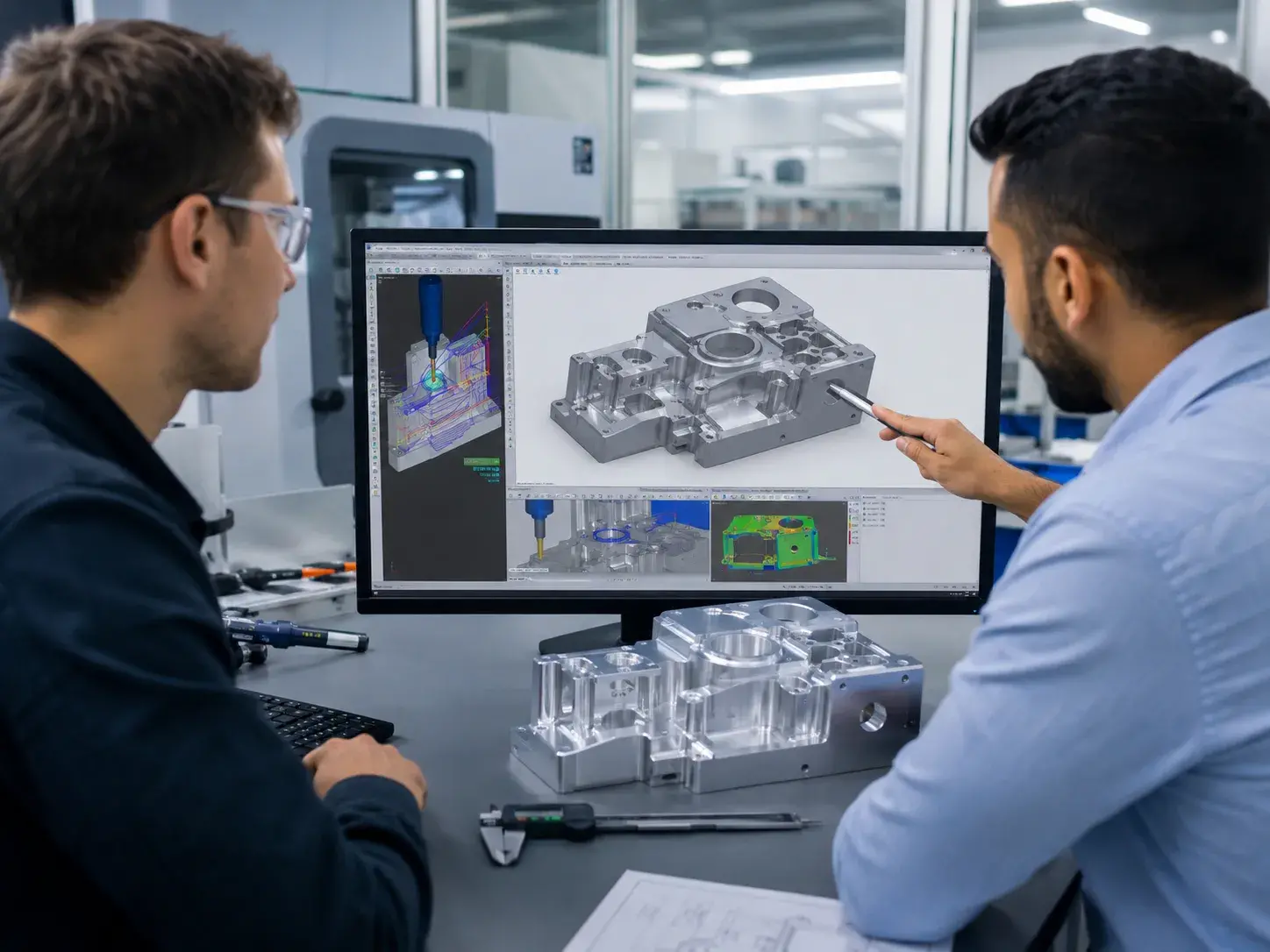
DFM review for complex CNC machined aluminum part using CAD CAM software

DFM stands for Design for Manufacturability, which involves examining a design from a manufacturing perspective to determine whether it is easy to machine, stable, and offers opportunities for cost reduction.

For complex CNC parts, a manufacturability review typically focuses on several aspects: whether cutting tools can access the part, whether there is a risk of interference, whether internal corners are too small, whether tolerances are reasonable, whether wall thickness is prone to deformation, and whether the number of clamping operations can be reduced.

In many cases, engineers do not recommend that customers make major design changes, but rather suggest minor adjustments.

For example:

  • Slightly increasing the radius (R) of an internal corner
  • Slightly relaxing a non-critical tolerance
  • Adding a little extra space to the opening of a deep cavity
  • Slightly optimizing the angle of a hole
  • Reordering the machining sequence for certain machined surfaces

These adjustments may seem minor, but they have a significant impact on machining efficiency and cost.

In new product development, the earlier an engineering review is conducted, the lower the cost of later modifications. This is especially true for prototypes, small-batch runs, and complex parts; involving machining engineers in the evaluation early on can reduce a great deal of unnecessary trial and error.


How YUANYI Supports Complex CNC Machining Projects

At YUANYI, we evaluate part geometry, materials, tolerances, surface finish requirements, and machining challenges based on our customers’ CAD files and drawings, and provide practical DFM recommendations. For complex 5-axis parts, we use CAM software to plan toolpaths and perform machine simulations to verify toolpaths, fixture clearance, and potential interference risks.

We support 3-axis, 4-axis, and 5-axis CNC machining, and we select the most appropriate machining method based on the part’s characteristics rather than simply recommending the most complex process. Our goal is to help customers find a more reasonable balance between quality, lead time, and cost.

Need DFM Advice for Your 5-Axis CNC Part?

Upload your CAD files and our engineers will review your design for tool access, tolerances, machining cost, and manufacturability.

Upload Your Drawing

Conclusion

Design has a significant impact on the results of five-axis machining.

A high-quality five-axis machine tool can perform complex machining operations, but if the part design does not take into account tool access, wall thickness, tolerances, and clamping methods, the machining process will still be difficult and costs will increase.

Good CNC part design should make it easier for the tool to access critical areas, ensure a more stable machining process, and make quality control easier.

Frequently Asked Questions

Not all parts are suitable for 5-axis CNC machining. Five-axis machining is better suited for complex surfaces, multi-faceted features, deep cavity structures, and high-precision complex parts. Simple parts are usually more economical to machine using three-axis or four-axis machining.

Sometimes. Five-axis machining can reduce the number of setups, improve machining efficiency, and reduce repeatability errors. However, if the part structure is very simple, five-axis machining may actually increase costs. The key is whether the part design is suitable for five-axis machining.

Common file formats include STEP, STP, IGES, X_T, and SolidWorks files. If 2D drawings are available, it is recommended to provide them as well, as drawings usually contain tolerances, material specifications, surface treatments, and critical dimensional requirements.

If the part has complex curved surfaces, deep cavities, multi-angle holes, multiple machined surfaces, or is difficult to machine using 3-axis clamping, 5-axis machining may be suitable. The most direct method is to send the CAD file to a machining engineer for evaluation.

This depends on the material, part size, structural complexity, and machining area. For high-precision parts, some critical dimensions can meet higher tolerance requirements, but it is not recommended to specify overly tight tolerances for all locations. Properly distinguishing between critical and ordinary dimensions is usually more beneficial for cost control.

Yes. For structurally complex prototype parts, 5-axis machining can reduce the number of clamping operations, shorten the machining cycle, and help the product team validate the design faster. However, if the prototype structure is simple, 3-axis or 4-axis machining can also be chosen.

Yes. Appropriately increasing internal angle radius, reducing deep and narrow cavities, optimizing wall thickness, and relaxing non-critical tolerances can all reduce machining time. Many cost optimizations are actually decided during the design phase.

Table of Contents
Discuss Your Complex Machining Requirements

Need Custom CNC Machined Parts?

From rapid prototypes to low-volume production, our engineering team can review your drawings and provide a manufacturing quote.

  • 24-Hour Quotation
  • DFM Engineering Support
  • No Minimum Order
  • ISO 9001 Certified
Request A Quote
Upload your drawing and get a quote within 24 hours.
