

Casting defects are unwanted irregularities that affect the appearance, dimensions, strength, or performance of a cast metal part. Common defects include porosity, shrinkage, blowholes, cold shuts, misruns, hot tears, inclusions, flash, and distortion.
Most casting defects result from problems with molten metal quality, mold design, filling, venting, temperature control, or solidification. Some are visible immediately, while internal defects may only be found through X-ray, ultrasonic inspection, or after CNC machining exposes material below the surface.
This guide covers 18 common casting defects, their causes, how to identify them, and practical ways to prevent them.
What Are Casting Defects?
A casting defect is an unintended irregularity that develops while molten metal fills a mold, solidifies, cools, or is removed from the mold.
Not every defect makes a casting unusable. Acceptability depends on the defect’s type, size, location, and the functional requirements of the part. Minor flash may simply require trimming, while internal shrinkage or cracking in a highly loaded area can compromise the entire component.
Different casting processes also produce different defect patterns. Sand-related defects are mainly associated with sand casting, while soldering and die sticking are more typical of die casting.
Common Casting Defects at a Glance
| Casting Defect | Typical Appearance | Main Cause | Common In | Typical Detection |
|---|---|---|---|---|
| Gas Porosity | Round voids | Trapped gas | Most processes | X-ray / CT |
| Shrinkage Porosity | Irregular cavities | Poor feeding | Most processes | X-ray / CT |
| Blowholes | Large smooth cavities | Trapped mold gas | Sand casting | Visual / X-ray |
| Pinholes | Small distributed holes | Dissolved gas | Aluminum casting | Visual / X-ray |
| Cold Shut | Seam or line | Poor fusion | Die / sand casting | Visual |
| Misrun | Incomplete shape | Premature solidification | Most processes | Visual |
| Hot Tear | Irregular crack | Restricted contraction | Sand / permanent mold | Visual / NDT |
| Slag/Oxide Inclusion | Embedded particles | Contaminated melt | Most processes | X-ray / sectioning |
| Sand Inclusion | Sand in casting | Mold erosion | Sand casting | Visual / X-ray |
| Cuts and Washes | Rough raised areas | Mold erosion | Sand casting | Visual |
| Metal Penetration | Rough fused surface | Metal enters sand pores | Sand casting | Visual |
| Scab | Raised irregular area | Mold surface failure | Sand casting | Visual |
| Rat Tail/Buckle | Irregular surface lines | Sand expansion | Sand casting | Visual |
| Mold Shift | Offset at parting line | Mold misalignment | Sand casting | Visual / dimensional |
| Core Shift | Displaced internal feature | Core movement | Sand casting | Dimensional / CT |
| Flash/Fin | Thin excess metal | Mold or die gap | Multiple processes | Visual |
| Warpage | Bent or twisted part | Uneven cooling | Most processes | Dimensional |
| Soldering | Metal stuck to die | Metal-die reaction | Die casting | Visual |
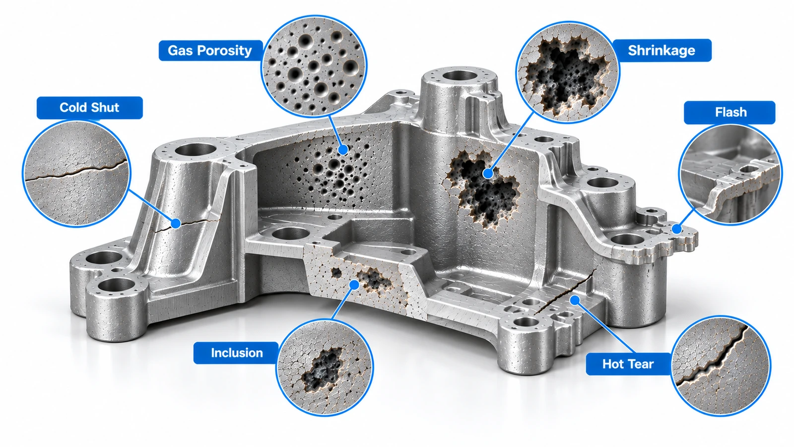
18 Common Types of Casting Defects
1. Gas Porosity
Gas porosity consists of rounded holes or voids inside or near the surface of a casting. It develops when gas becomes trapped in molten metal and cannot escape before solidification.
Common causes:
- Poor mold or die venting
- Turbulent metal flow
- Dissolved gases
- Excess moisture
- Improper pouring or injection conditions
How to prevent it: Improve venting, reduce turbulence, control moisture, maintain suitable casting temperatures, and degas the molten metal when required.
Gas porosity is particularly important in pressure-tight components and parts that will undergo substantial CNC machining.
2. Shrinkage Porosity
Shrinkage porosity occurs when metal contracts during solidification but insufficient liquid metal is available to feed the shrinking area.
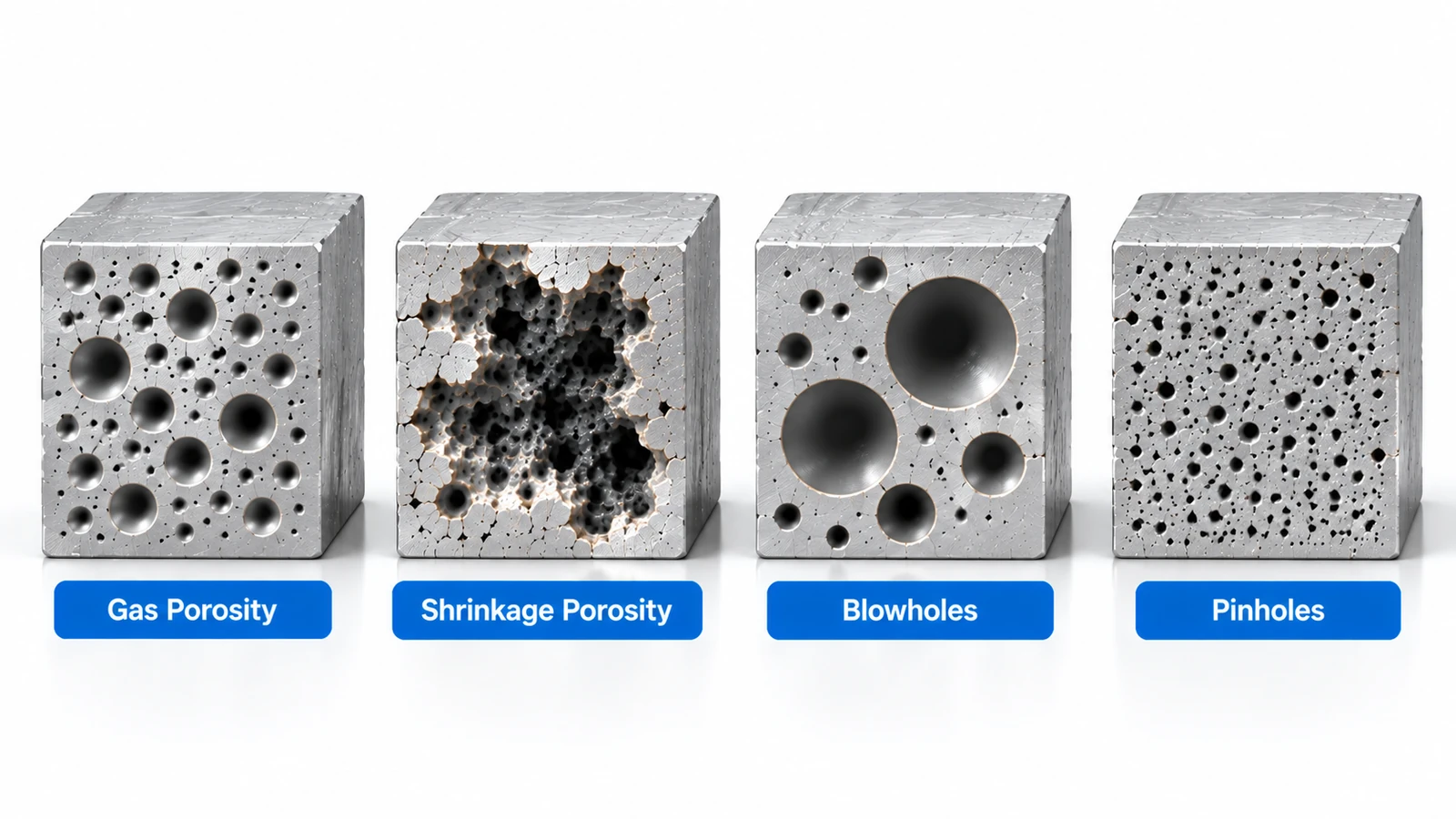
Unlike gas porosity, which usually forms smoother rounded holes, shrinkage cavities tend to be irregular or angular.
Common causes:
- Poor riser or feeder design
- Isolated thick sections
- Uneven cooling
- Inadequate metal feeding
How to prevent it: Optimize risers, gates, wall transitions, and cooling so solidification occurs in a controlled direction and molten metal can continue feeding shrinking areas.
3. Blowholes
Blowholes are relatively large, smooth cavities caused by trapped gas. They are particularly common in sand casting when gases generated by the mold cannot escape.
Common causes:
- Excess moisture in molding sand
- Poor mold permeability
- Inadequate venting
- Gas-producing binders
- Damp cores
How to prevent it: Control sand moisture, improve permeability and venting, dry cores properly, and reduce unnecessary gas generation.
Gas porosity vs blowholes: Gas porosity is a broad category of gas-related voids. Blowholes are typically larger gas cavities and are commonly associated with mold gases in sand casting.
4. Pinholes
Pinholes are very small gas cavities that often appear in groups near or beneath the casting surface.
They are commonly associated with gases dissolved in molten metal. Aluminum alloys, for example, can absorb hydrogen in the liquid state and release it as the metal solidifies.
How to prevent it: Keep the melt clean, minimize moisture exposure, control furnace conditions, and use appropriate degassing procedures.
Compared with blowholes, pinholes are generally smaller, more numerous, and more widely distributed.
5. Cold Shut
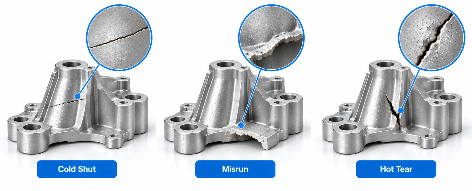
A cold shut forms when two streams of molten metal meet but fail to fuse completely. It often appears as a thin seam or line on the casting surface.
Common causes:
- Low pouring temperature
- Slow filling
- Thin sections
- Long flow paths
- Poor gating design
How to prevent it: Maintain adequate metal temperature, improve filling conditions, optimize gate locations, and avoid unnecessarily thin sections that cool too quickly.
6. Misrun
A misrun occurs when molten metal solidifies before completely filling the mold cavity. The resulting casting may have missing corners, edges, or entire sections.
Common causes:
- Low metal temperature
- Slow filling
- Poor fluidity
- Thin walls
- Improper gate location
How to prevent it: Improve filling efficiency, maintain appropriate pouring temperature, optimize gating, and design wall thicknesses suitable for the selected casting process.
A cold shut means metal reached the area but failed to fuse properly; a misrun means the metal did not completely fill the cavity.
7. Hot Tears and Hot Cracking
Hot tears are irregular cracks that form during the later stages of solidification when the metal is contracting but does not yet have enough strength to withstand the resulting stress.
They commonly develop around abrupt section changes, sharp corners, and areas where contraction is restricted.
How to prevent it: Use smoother thickness transitions, adequate fillets, more uniform sections, and mold designs that allow the casting to contract more freely.
8. Slag and Oxide Inclusions
Inclusions occur when nonmetallic material becomes trapped inside the casting. These contaminants may include slag, oxide films, refractory particles, or other foreign material.
Inclusions can reduce mechanical properties and may interfere with machining or finishing.
Common causes:
- Dirty molten metal
- Oxidation
- Turbulent pouring
- Poor skimming or filtration
How to prevent it: Maintain melt cleanliness, remove slag, minimize turbulence, and use filtration where appropriate.
9. Sand Inclusion
Sand inclusion occurs when particles from a sand mold or core break away and become trapped in the solidifying metal.
It may appear as embedded sand, rough cavities, or irregular surface defects.
How to prevent it: Improve mold strength, control sand properties, reduce excessive metal velocity, and prevent molten metal from directly eroding vulnerable mold surfaces.
10. Cuts and Washes
Cuts and washes occur when fast-moving molten metal erodes the surface of a sand mold. The damaged mold can create rough, raised areas on the casting and introduce loose sand into the metal.
How to prevent it: Reduce excessive metal velocity, improve mold strength, and position gates so molten metal does not directly strike weak mold surfaces.
11. Metal Penetration
Metal penetration occurs when molten metal enters the spaces between sand grains and solidifies there, producing a rough surface that can be difficult to clean.
Common causes:
- Coarse molding sand
- High pouring temperature
- Poor mold compaction
- Excessive metallostatic pressure
How to prevent it: Use appropriate sand grain size, improve mold compaction, control pouring temperature, and apply suitable mold coatings when necessary.
12. Scab
A scab is an irregular raised area formed when part of the mold surface cracks or lifts and molten metal flows underneath it.
It is mainly associated with sand mold strength, moisture, and thermal expansion.
How to prevent it: Control sand properties and moisture, ensure proper mold compaction, and improve mold surface stability.
13. Rat Tails and Buckles
Rat tails are narrow, irregular lines on a casting surface, while buckles are broader surface distortions. Both can result from expansion of molding sand when exposed to molten metal.
How to prevent it: Optimize sand composition and moisture, improve mold collapsibility, and control excessive expansion of the mold surface.
14. Mold Shift or Mismatch
Mold shift occurs when the two halves of a mold are not properly aligned, creating an offset at the parting line and potentially causing dimensional errors.
Common causes:
- Incorrect mold assembly
- Worn locating features
- Poor clamping
- Mold movement during pouring
How to prevent it: Maintain locating features, verify mold alignment, and provide adequate clamping before pouring.
15. Core Shift
Cores are used to create internal holes, cavities, and passages. If a core moves during casting, these features can be displaced from their intended positions.
The result may be incorrect bore locations or uneven wall thickness.
How to prevent it: Secure and locate cores properly, provide sufficient support, and account for buoyancy forces from the molten metal.
16. Flash and Fins
Flash is thin excess metal that forms along mold parting lines, die joints, or gaps around cores.
Small amounts of flash can usually be removed during trimming or CNC machining. Excessive flash, however, may indicate a tooling or process problem.
Common causes:
- Poor mold or die closure
- Worn tooling
- Misalignment
- Excessive casting pressure
How to prevent it: Maintain mold and die surfaces, ensure correct alignment and clamping, and control casting pressure.
17. Warpage and Distortion
Warpage occurs when a casting bends, twists, or changes shape during cooling.
Uneven section thicknesses and cooling rates can generate residual stresses that distort the component.
How to prevent it: Maintain more uniform wall thickness, avoid abrupt geometry changes, control cooling conditions, and provide appropriate support where necessary.
18. Soldering and Die Sticking
Soldering occurs primarily in die casting when molten metal adheres or reacts with the die surface. This can make the casting difficult to eject and damage both the part and die.
It is particularly relevant in aluminum die casting.
Common causes:
- Excessive die temperature
- High metal temperature
- Insufficient lubrication
- High local metal velocity
- Worn die surfaces
How to prevent it: Control die and melt temperatures, maintain proper lubrication, optimize metal flow, and keep die surfaces in good condition.
What Causes Casting Defects?
Although individual defects have different mechanisms, most originate from five areas:
Molten metal quality: Gas absorption, oxides, slag, and other contaminants can produce porosity and inclusions.
Mold or die condition: Poor venting, weak molds, worn tooling, and incorrect alignment can create surface and dimensional defects.
Filling conditions: Filling too slowly can cause misruns and cold shuts, while excessive turbulence can trap gas, form oxide films, or damage sand molds.
Solidification and cooling: Poor feeding and uneven cooling can cause shrinkage, hot tears, residual stress, and distortion.
Part design: Very thin walls, sharp corners, isolated heavy sections, and abrupt thickness changes make controlled filling and solidification more difficult.
Preventing casting defects therefore requires control of the entire process rather than adjustment of a single parameter.
How Are Casting Defects Detected?
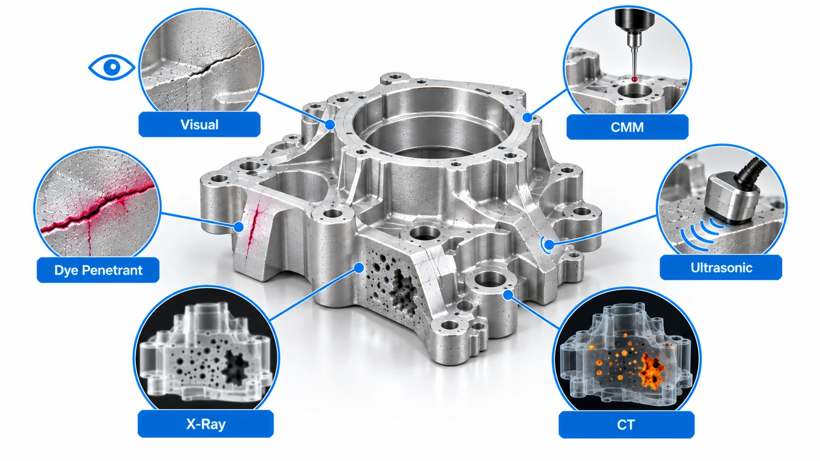
The correct inspection method depends on whether the defect is on the surface or inside the casting.
Visual Inspection
Used to identify obvious defects such as flash, misruns, cold shuts, sand defects, surface cracks, and severe distortion.
Dimensional Inspection
Calipers, micrometers, gauges, and CMMs can identify mold shift, core shift, warpage, and dimensional deviations.
Dye Penetrant Testing
Dye penetrant testing can reveal small surface-breaking cracks and discontinuities in nonporous materials.
Magnetic Particle Testing
For suitable ferromagnetic materials, magnetic particle inspection can identify surface and near-surface discontinuities.
Ultrasonic Testing
Ultrasonic testing uses high-frequency sound waves to locate internal discontinuities and is useful for many thicker cast components.
X-Ray and Radiographic Testing
Radiographic inspection is commonly used to identify internal porosity, shrinkage cavities, inclusions, and certain cracks without destroying the part.
CT Scanning
Industrial CT creates a three-dimensional view of internal geometry and defects. It is particularly useful for complex or high-value castings where internal defect location and size must be understood precisely.
How to Prevent Casting Defects
There is no single method that prevents every casting defect. Reliable casting production depends on controlling material, tooling, filling, solidification, and inspection together.
Key measures include:
- Keep molten metal clean and control dissolved gases.
- Maintain appropriate pouring or injection temperatures.
- Design gates and runners for stable metal flow.
- Provide adequate venting.
- Use properly designed risers and feeders.
- Avoid abrupt changes in wall thickness.
- Add suitable fillets at critical transitions.
- Control mold, die, and cooling temperatures.
- Maintain molds, dies, cores, and locating features.
- Use suitable inspection methods for critical parts.
For repeat production, manufacturers should also track defect patterns. Repeated defects often point to a systematic issue in tooling, material preparation, design, or process settings.
Can CNC Machining Remove Casting Defects?
CNC machining can remove some surface-related casting imperfections, but it cannot repair structural defects inside the material.
Machining can typically remove or correct:
- Flash and fins
- Parting lines
- Excess machining stock
- Minor surface irregularities
- Certain shallow surface defects
- Dimensional stock left intentionally for finishing
However, machining cannot reliably eliminate:
- Deep gas porosity
- Shrinkage cavities
- Internal inclusions
- Hot tears
- Structural cracks
In fact, machining can expose defects that were previously hidden.
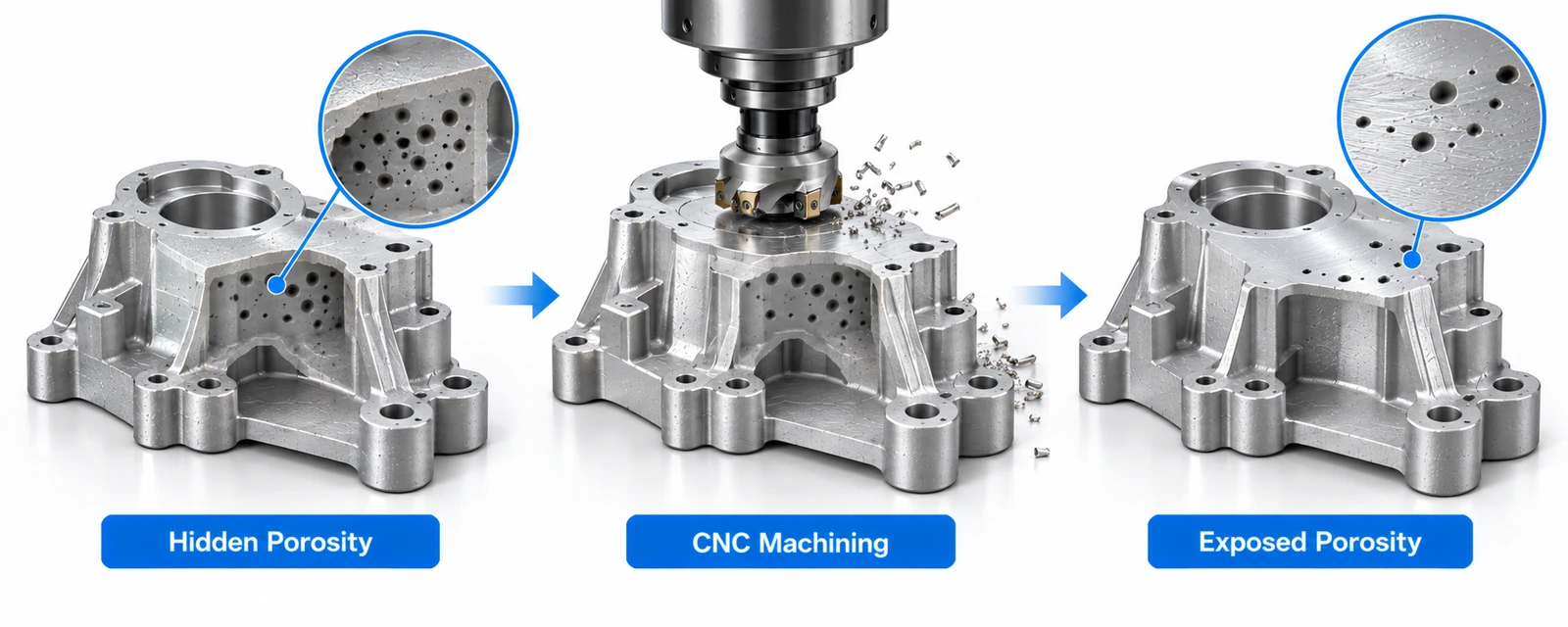
For example, a cast aluminum housing may look completely acceptable before machining. After a sealing face or precision bore is milled, internal porosity can become exposed on the finished surface.
This does not necessarily mean the machining operation caused the defect—the void may have already existed inside the casting.
For cast components requiring precision machining, casting quality, machining allowance, datum selection, final tolerances, and inspection requirements should be considered together during part development.
Casting Defects vs Machining Defects
Casting and machining defects can sometimes look similar, especially after a cast component has been machined.
The key difference is where the problem originates.
Casting defects develop during metal filling, solidification, cooling, or interaction with the mold. Examples include porosity, shrinkage, inclusions, cold shuts, and hot tears.
Machining defects occur during material removal and are more commonly related to cutting parameters, worn tools, vibration, workholding, chip evacuation, or programming.
For example, a pore exposed after milling may appear to be a machining problem even though the cavity was already present below the cast surface.
Correctly identifying the defect source helps avoid changing CNC machining parameters when the actual problem originates upstream in the casting process.
CNC Machining of Cast Parts
Many cast components still require CNC machining for features such as precision bores, sealing surfaces, threads, bearing seats, and mounting faces.
For these parts, machining allowance and critical feature locations should be considered during casting design. Areas that require tight tolerances should have sufficient material for finishing without unnecessarily increasing machining time.
YuanYi provides CNC milling, turning, and multi-axis machining for metal parts, including secondary machining of cast components. Combining suitable casting quality with controlled machining and dimensional inspection helps achieve the required tolerances and surface finish on critical features.
FAQs About Casting Defects
Common casting defects include porosity, shrinkage, blowholes, pinholes, cold shuts, misruns, hot tears, inclusions, mold shift, core shift, flash, and warpage. The defects most likely to occur depend on the alloy and casting process.
Porosity can result from trapped gas, dissolved gases, poor venting, turbulent filling, or insufficient feeding during solidification. Gas porosity and shrinkage porosity have different causes and require different corrective actions.
Gas porosity forms when gas becomes trapped in the metal and typically produces relatively smooth, rounded cavities. Shrinkage occurs when solidifying metal contracts without sufficient liquid metal feeding and generally produces more irregular cavities.
Cold shuts occur when separate streams of molten metal meet but fail to fuse. Common causes include low metal temperature, slow filling, thin walls, long flow paths, and poor gating design.
The severity depends on the application and defect location. Cosmetic surface defects may have little effect on function, while cracks, shrinkage cavities, inclusions, or significant porosity in highly stressed or pressure-sealing areas can make a component unacceptable.
For critical parts, defect acceptance should therefore be based on engineering requirements rather than appearance alone.
Conclusion
Casting defects can result from molten metal quality, mold design, filling, solidification, cooling, or part geometry. Identifying the defect correctly is the first step toward determining its cause and preventing it from recurring.
For cast parts that require tight tolerances, the manufacturing process should also account for what happens after casting. Machining allowance, datum selection, inspection, and final CNC operations all influence the quality of the finished component.
A sound casting provides the foundation; precision machining brings critical features to their required dimensions, tolerances, and surface finish.



