

Ball bearing sizes are defined by three dimensions: inner diameter (ID), outer diameter (OD), and width. For example, a 6205 ball bearing measures 25 × 52 × 15 mm. These dimensions help engineers select bearings that fit their shafts and housings.
This guide provides common metric ball bearing size charts for the 6000, 6200, 6300, 6800, and 6900 series. It also explains bearing numbers, measurement methods, size selection, and the shaft and housing fits needed for reliable installation.
Common Ball Bearing Sizes Chart (mm)
The following ball bearing sizes charts list the standard boundary dimensions of common single-row deep groove ball bearings.
- d (ID): Inner diameter or bore
- D (OD): Outside diameter
- B: Bearing width
All dimensions are in millimeters. These are nominal reference dimensions, not manufacturing manufacturing tolerance limits. Confirm the exact bearing designation and manufacturer’s drawing before finalizing a design.
6000 Series Ball Bearing Size Chart
The 6000 series offers relatively compact dimensions and is commonly used in electric motors, fans, pumps, and general machinery.
| Bearing No. | ID (mm) | OD (mm) | Width (mm) |
|---|---|---|---|
| 6000 | 10 | 26 | 8 |
| 6001 | 12 | 28 | 8 |
| 6002 | 15 | 32 | 9 |
| 6003 | 17 | 35 | 10 |
| 6004 | 20 | 42 | 12 |
| 6005 | 25 | 47 | 12 |
| 6006 | 30 | 55 | 13 |
| 6007 | 35 | 62 | 14 |
| 6008 | 40 | 68 | 15 |
| 6009 | 45 | 75 | 16 |
| 6010 | 50 | 80 | 16 |
| 6011 | 55 | 90 | 18 |
| 6012 | 60 | 95 | 18 |
6200 Series Ball Bearing Size Chart
The 6200 series is widely used in industrial equipment, motors, gearboxes, and mechanical assemblies. It generally provides a larger bearing cross-section than the 6000 series at the same bore diameter.
| Bearing No. | ID (mm) | OD (mm) | Width (mm) |
|---|---|---|---|
| 6200 | 10 | 30 | 9 |
| 6201 | 12 | 32 | 10 |
| 6202 | 15 | 35 | 11 |
| 6203 | 17 | 40 | 12 |
| 6204 | 20 | 47 | 14 |
| 6205 | 25 | 52 | 15 |
| 6206 | 30 | 62 | 16 |
| 6207 | 35 | 72 | 17 |
| 6208 | 40 | 80 | 18 |
| 6209 | 45 | 85 | 19 |
| 6210 | 50 | 90 | 20 |
| 6211 | 55 | 100 | 21 |
| 6212 | 60 | 110 | 22 |
6300 Series Ball Bearing Size Chart
The 6300 series has a larger cross-section than the 6000 and 6200 series for the same shaft diameter. It is often considered where higher load capacity is needed and additional installation space is available.
| Bearing No. | ID (mm) | OD (mm) | Width (mm) |
|---|---|---|---|
| 6300 | 10 | 35 | 11 |
| 6301 | 12 | 37 | 12 |
| 6302 | 15 | 42 | 13 |
| 6303 | 17 | 47 | 14 |
| 6304 | 20 | 52 | 15 |
| 6305 | 25 | 62 | 17 |
| 6306 | 30 | 72 | 19 |
| 6307 | 35 | 80 | 21 |
| 6308 | 40 | 90 | 23 |
| 6309 | 45 | 100 | 25 |
| 6310 | 50 | 110 | 27 |
| 6311 | 55 | 120 | 29 |
| 6312 | 60 | 130 | 31 |
6800 and 6900 Thin-Section Bearing Sizes
The 6800 and 6900 series are designed for applications where radial space is limited, such as compact robotics, instruments, and lightweight mechanisms.
6800 Series
| Bearing No. | ID (mm) | OD (mm) | Width (mm) |
|---|---|---|---|
| 6800 | 10 | 19 | 5 |
| 6801 | 12 | 21 | 5 |
| 6802 | 15 | 24 | 5 |
| 6803 | 17 | 26 | 5 |
| 6804 | 20 | 32 | 7 |
| 6805 | 25 | 37 | 7 |
| 6806 | 30 | 42 | 7 |
| 6807 | 35 | 47 | 7 |
| 6808 | 40 | 52 | 7 |
| 6809 | 45 | 58 | 7 |
| 6810 | 50 | 65 | 7 |
6900 Series
| Bearing No. | ID (mm) | OD (mm) | Width (mm) |
|---|---|---|---|
| 6900 | 10 | 22 | 6 |
| 6901 | 12 | 24 | 6 |
| 6902 | 15 | 28 | 7 |
| 6903 | 17 | 30 | 7 |
| 6904 | 20 | 37 | 9 |
| 6905 | 25 | 42 | 9 |
| 6906 | 30 | 47 | 9 |
| 6907 | 35 | 55 | 10 |
| 6908 | 40 | 62 | 12 |
| 6909 | 45 | 68 | 12 |
| 6910 | 50 | 72 | 12 |
A common miniature bearing is the 608, with dimensions of 8 × 22 × 7 mm. Miniature bearings such as the 608 use a different designation format and are not included in the main 6000–6300 tables above.
How to Measure Ball Bearing Dimensions
When a bearing number is missing or unreadable, three measurements can help identify its size.
1. Measure the Inner Diameter (ID)
Use a caliper to measure the bore of the inner ring. This dimension corresponds to the shaft’s nominal diameter.
For example, a bearing with a nominal 25 mm bore may belong to several different series, including 6005, 6205, and 6305.
2. Measure the Outer Diameter (OD)
Measure across the outer ring at its widest diameter. The OD determines the nominal size of the bearing housing bore.
Avoid measuring over external retaining rings or other accessories.
3. Measure the Bearing Width
Measure between the flat side faces of the bearing rings.
For example, if you measure approximately:
- ID: 25 mm
- OD: 52 mm
- Width: 15 mm
The bearing’s boundary dimensions match a standard 6205 bearing.
Important: Caliper measurements are useful for identifying bearing sizes, but they should not be used to establish precision bearing tolerances. Worn, damaged, or corroded bearings may also produce misleading measurements.
How to Read Ball Bearing Numbers and Codes
Bearing numbers identify the bearing type, dimension series, and bore size. Additional letters or numbers indicate features such as sealing, internal clearance, or special designs.
Consider the designation 6205-2RS-C3.
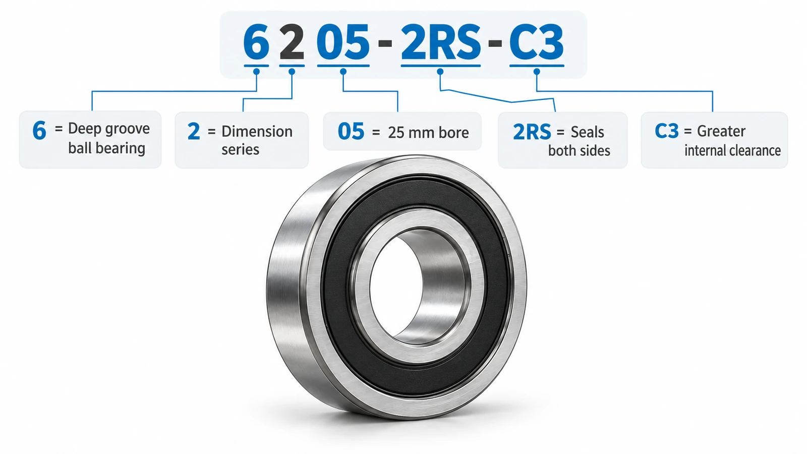
| Code | Meaning |
|---|---|
| 6 | Single-row deep groove ball bearing |
| 2 | Dimension series |
| 05 | Nominal bore diameter of 25 mm |
| 2RS | Rubber contact seals on both sides; terminology can vary by manufacturer |
| C3 | Radial internal clearance greater than Normal |
The bore code is particularly useful for understanding metric bearing sizes.
Bearing Bore Code Chart
| Bore Code | Bore Diameter |
|---|---|
| 00 | 10 mm |
| 01 | 12 mm |
| 02 | 15 mm |
| 03 | 17 mm |
| 04 | 20 mm |
| 05 | 25 mm |
| 06 | 30 mm |
| 07 | 35 mm |
| 08 | 40 mm |
| 09 | 45 mm |
| 10 | 50 mm |
| 12 | 60 mm |
For many standard metric bearing designations with bore codes from 04 onward:
Bore diameter = Bore code × 5 mm
For example, the last two digits of 6206 are 06, giving a 30 mm bore.
This rule has exceptions, especially for miniature, special-bore, and nonstandard bearings. Always consult the relevant product designation system.
ZZ vs. 2RS vs. Open Bearings
| Type | Construction | Typical Consideration |
|---|---|---|
| Open | No integrated shields or seals | Allows external lubrication |
| ZZ / 2Z | Metal shields on both sides | Low-friction protection against larger contaminants |
| 2RS | Contact seals on both sides | Improved resistance to dirt and moisture, with additional seal friction |
Suffixes may vary between manufacturers. Bearings with identical boundary dimensions may still differ in sealing, speed capability, lubrication, and internal clearance.
6000 vs. 6200 vs. 6300 Bearings: What's the Difference?
These bearing series differ mainly in their cross-sectional dimensions.
A useful comparison is to look at bearings with the same 25 mm inner diameter.
| Bearing | ID | OD | Width | Relative Size |
|---|---|---|---|---|
| 6805 | 25 | 37 | 7 | Very thin |
| 6905 | 25 | 42 | 9 | Thin |
| 6005 | 25 | 47 | 12 | Compact |
| 6205 | 25 | 52 | 15 | Medium |
| 6305 | 25 | 62 | 17 | Larger section |
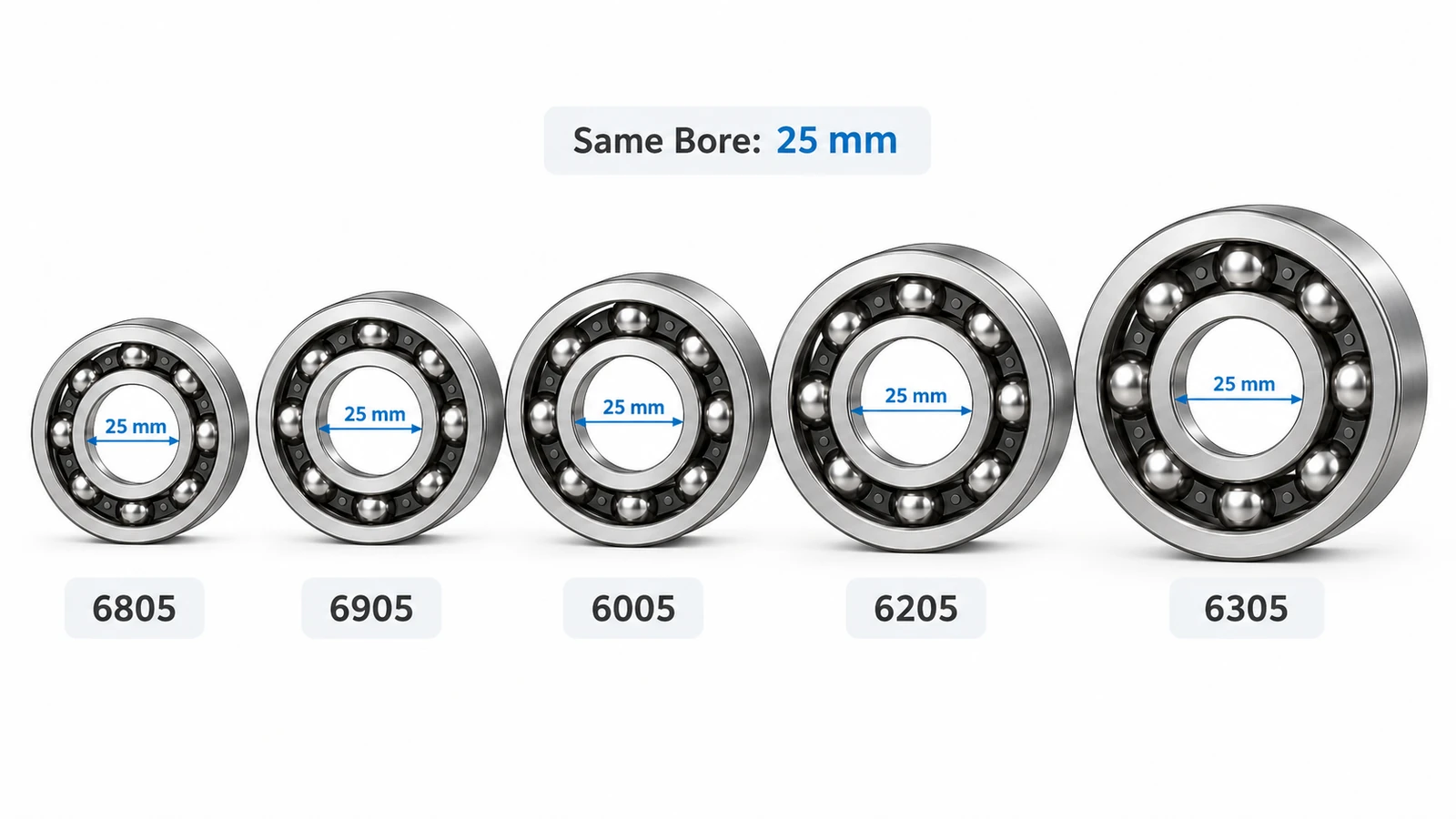
All five bearings can accommodate a nominal 25 mm shaft, but they require different housing diameters and axial installation spaces.
In general, larger bearing cross-sections can accommodate larger rolling elements and may provide higher load capacity within comparable bearing designs. However, exact load ratings, operating speeds, friction, and service life depend on the specific bearing construction.
Can a 6005 replace a 6205?
Not as a direct drop-in replacement in the same housing. Although both have a 25 mm bore, their outside diameters and widths differ.
Even when two bearings have identical overall dimensions, their load ratings, sealing, clearance, and operating characteristics should be checked before substitution.
How to Choose the Right Ball Bearing Size
Selecting a bearing involves more than matching the shaft diameter. Follow these practical steps.
Step 1 — Confirm the shaft diameter.
Start with the nominal shaft diameter and identify bearing models with matching bores.
Step 2 — Check available installation space.
Compare the bearing’s outside diameter and width against the available housing dimensions.
Step 3 — Determine the operating loads.
Consider radial loads, axial loads, shock loading, and load direction. Use the manufacturer’s ratings and life calculation guidance where required.
Step 4 — Check rotational speed and lubrication.
Confirm that the selected bearing, seal design, grease or oil, and operating temperature are suitable for the expected speed.
Step 5 — Select sealing and internal clearance.
An open, shielded, or sealed bearing may be appropriate depending on contamination, lubrication, and maintenance requirements.
Internal clearance must also account for operating temperature and the reduction in clearance caused by interference fits.
Step 6 — Confirm mounting and manufacturing requirements.
Before releasing shaft or housing drawings, specify the required fits, shoulders, chamfers, chamfers, surface finish, and inspection requirements.
For replacement bearings, confirm the complete original designation whenever possible rather than relying on dimensions alone.
Bearing Fits: Shaft and Housing Tolerances
A bearing’s listed dimensions are nominal. They are not the finished machining dimensions for the shaft and housing.
For example, a 6205 bearing has:
- Nominal bore: Ø25 mm
- Nominal outside diameter: Ø52 mm
- Width: 15 mm
However, this does not mean the shaft should automatically be machined to exactly Ø25.000 mm or the housing to Ø52.000 mm.
The appropriate fit depends on which ring rotates relative to the load, bearing loads, shaft and housing materials, temperature, and mounting requirements.
Clearance, Transition, and Interference Fits
| Fit Type | Description | Main Consideration |
|---|---|---|
| Clearance fit | A gap remains between mating parts within the specified limits | Facilitates assembly or axial movement |
| Transition fit | Manufacturing tolerances can result in clearance or interference | Provides controlled location with limited assembly force |
| Interference fit | The mating parts overlap dimensionally before assembly | Helps prevent ring movement or creep |
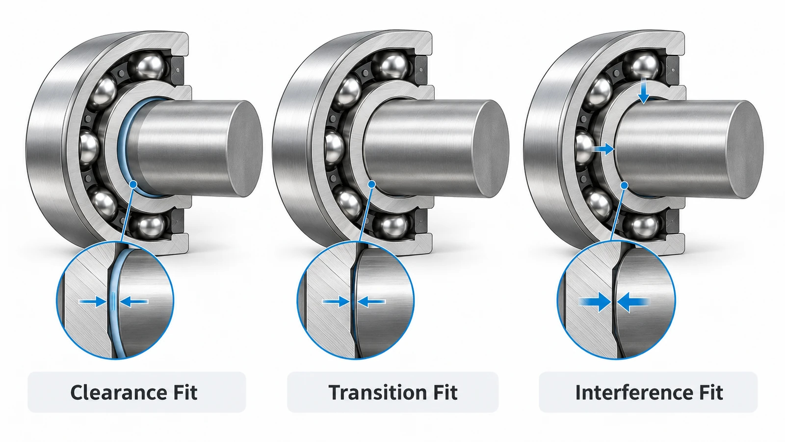
For applications where a bearing ring experiences a rotating load relative to that ring, an interference fit is commonly considered to prevent movement between mating surfaces.
A ring under a stationary load may permit a looser fit, depending on the design.
Common ISO shaft tolerance zones include h6, j6, k6, and m6, while housing tolerance zones include H7, J7, K7, and M7.
These are possible tolerance designations, not universal bearing-fit recommendations. Selecting a specific fit requires checking the bearing manufacturer’s application tables and the assembly’s operating conditions.
An excessively tight fit can reduce radial internal clearance and increase bearing stress. An excessively loose fit can cause creep, fretting, vibration, and wear.
Example: Designing a Housing for a 6205 Bearing
Suppose a mechanical assembly uses a standard 6205 bearing mounted on a steel shaft inside an inside an aluminum housing.
The nominal bearing dimensions are already known: 25 × 52 × 15 mm.
Before machining, the engineer should determine:
- Whether the inner or outer ring experiences a rotating load
- The magnitude and direction of the operating loads
- The effect of steel and aluminum thermal expansion
- The required shaft and housing fit classes
- The required shoulder geometry and axial retention
- The inspection method for both bearing seats
Because aluminum expands more than steel as temperature rises, the operating fit of the outer ring may change significantly.
The final machining dimensions should therefore come from the selected fit and operating requirements—not simply from the bearing size chart.
CNC Machining Considerations for Bearing Seats
Even correctly selected bearings can experience vibration, noise, and reduced service life when shaft and housing seats are poorly machined.
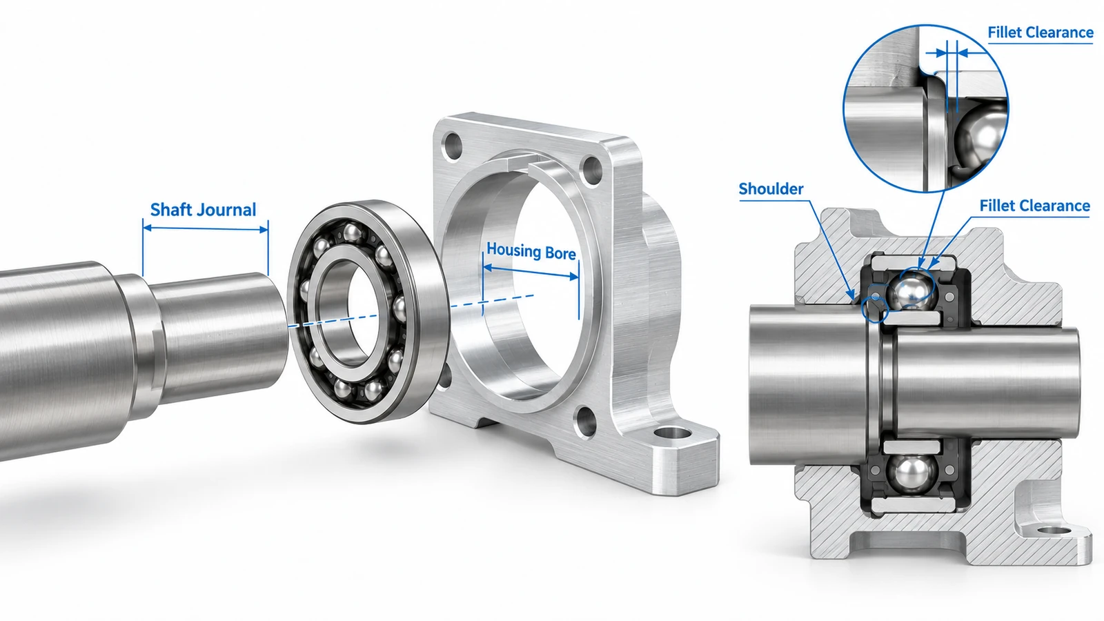
Several features require attention beyond the nominal diameter.
| Machining Feature | Why It Matters |
|---|---|
| Diameter tolerance | Controls the intended clearance or interference |
| Roundness and cylindricity | Reduce localized ring distortion |
| Coaxiality and runout | Help maintain alignment of bearing positions |
| Shoulder perpendicularity | Supports proper axial seating |
| Surface roughness | Influences contact conditions and effective interference |
| Fillet radius and chamfers | Prevent interference with bearing corner radii |
| Burr removal | Supports clean seating and reliable assembly |
CNC Turning for Bearing Shafts
Precision CNC turning is commonly used to produce bearing journals, stepped shafts, sleeves, and motor shaft features.
Important considerations include maintaining consistent journal diameters, controlling runout between bearing positions, and machining shoulders accurately.
For shaft components with demanding dimensional and geometric requirements, finishing or grinding may be necessary after turning.
Learn more about our CNC Turning Services.
CNC Milling and Boring for Bearing Housings
Bearing housings may require precision boring, pocket milling, face machining, and drilling.
In gearbox housings, motor housings, and robotic assemblies, the position and alignment of multiple bearing bores can be just as important as their individual diameters.
Suitable workholding, machining sequences, and inspection methods help limit geometric errors.
Learn more about our CNC Milling Services.
For precision bearing-seat components, inspection should verify the drawing’s specified dimensional and dimensional and geometric tolerances rather than checking bore diameter alone.
Conclusion
A ball bearing size chart helps identify standard bearing dimensions, compare different series, and select suitable replacement or design options. However, matching the inner diameter, outer diameter, and width is only the first step.
Reliable bearing performance also depends on load capacity, speed, internal clearance, correct shaft and housing fits, and the geometric accuracy of machined bearing seats.
At YuanYi Precision Manufacturing, we provide CNC turning and milling services for custom shafts, bearing housings, and precision mechanical components. If your design requires accurately machined bearing interfaces, contact our team with your drawings and specifications for a manufacturing review.
Frequently Asked Questions
A standard 6205 deep groove ball bearing has a 25 mm inner diameter, 52 mm outside diameter, and 15 mm width.
A 6204 measures 20 × 47 × 14 mm, while a 6205 measures 25 × 52 × 15 mm. They have different bore, outside diameter, and width dimensions and are not direct replacements for each other.
Measure the bore diameter, outside diameter, and width using a caliper. Compare these dimensions against a bearing size chart, then verify the bearing type, seals, and other features before selecting a replacement.
Not always. The required fit depends primarily on load conditions, the ring’s motion relative to the load, operating temperature, and mounting requirements. Some applications need an interference fit, while others permit clearance or transition fits.
Not necessarily. Bearings with identical boundary dimensions may have different load ratings, internal clearances, sealing arrangements, tolerance classes, and speed limits. These specifications must also match the application.



