

GD&T, or Geometric Dimensioning and Tolerancing, defines how much a part’s shape, orientation, location, and rotational features are allowed to vary from their ideal geometry.
For CNC machining, GD&T does much more than describe drawing requirements. It directly affects how a part is fixtured, how many machining setups are required, which features should be machined together, how the part is inspected, and ultimately how much the part costs to manufacture.
A tight flatness requirement may require additional finishing. A position tolerance may require precise datum control and CMM inspection. A runout requirement may force multiple cylindrical features to be machined in one setup.
The goal of GD&T is therefore not simply to make tolerances tighter. It is to define the geometric variation that actually matters to part function while allowing reasonable manufacturing freedom.
If you are looking for a complete overview of common drawing symbols, see our Engineering Drawing Symbols and Abbreviations guide.
What Is GD&T?
GD&T is a symbolic language used on engineering drawings to control the geometry of a part. Instead of defining only the size of a feature, it defines the shape of the feature, its orientation, its location, and how much it is allowed to vary as the part rotates or is assembled.
The standard divides geometric controls into five groups. There are fourteen geometric characteristics in total:
- Form — straightness, flatness, circularity, cylindricity
- Orientation — parallelism, perpendicularity, angularity
- Location — position
- Profile — profile of a line and profile of a surface
- Runout — circular runout and total runout
You do not need to memorize every symbol to understand how GD&T affects machining. The more important question is:
What physical relationship is the drawing trying to control?
That question connects the drawing to the manufacturing process, because every geometric control has to be produced by a real setup and verified by a real inspection method.
GD&T Standards: ASME Y14.5 vs ISO 1101
GD&T is defined by standards, and the drawing should state which one applies.
ASME Y14.5 is the most widely used standard for mechanical drawings. ASME Y14.5-2018 is the current edition. In the 2018 edition, concentricity and symmetry were removed and are now expressed with position and runout controls. Old drawings may still carry these symbols from earlier editions such as ASME Y14.5-1994 or Y14.5-2009.
ISO 1101 defines geometric tolerancing internationally and is broadly equivalent in intent, but the default interpretation of some rules differs from ASME. ISO 2768 covers general tolerances, which apply when no individual tolerance is shown on the drawing.
For manufacturing, the practical points are:
- Confirm which standard and which edition the drawing invokes before quoting
- Do not mix ASME and ISO interpretation on the same drawing
- Check whether general tolerances (ISO 2768 or a drawing note) already cover non-critical features
- Re-check legacy drawings, because controls that were once common may now be interpreted differently
Standard selection also affects how tolerances are expressed and inspected. For a wider look at accuracy classes, see our guide to CNC machining tolerances.
What Does GD&T Mean for CNC Machining?
Traditional plus/minus (bilateral) dimensional tolerances mainly control size and distance.
GD&T adds control over the actual geometry and the relationship between features.
For example, a drawing may specify:
- A surface must be flat
- A hole pattern must remain within a positional tolerance zone
- A bore must be perpendicular to a mounting face
- A shaft must remain within a runout limit
- A complex 3D surface must stay within a profile tolerance
These requirements influence CNC process planning because the machinist must determine how to establish datums, hold the workpiece, sequence operations, and verify the finished geometry.
How to Read a GD&T Feature Control Frame
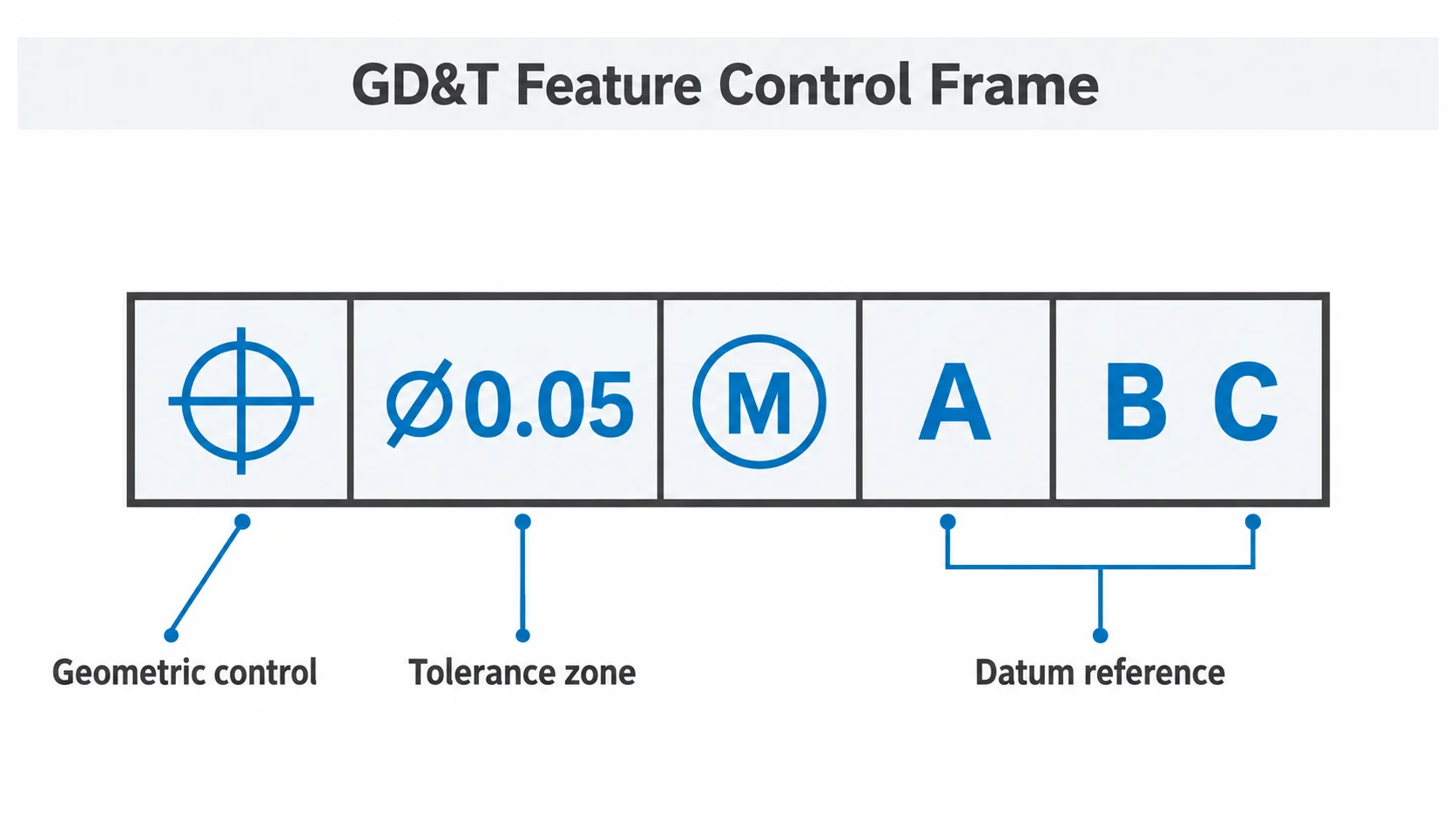
A feature control frame tells the manufacturer what geometric characteristic is controlled, how large the tolerance zone is, and which datums establish the reference system.
A typical position callout may look like:
Position | ∅0.05 | M | A | B | C
Each section communicates something different.
Position identifies the geometric control.
∅0.05 defines a cylindrical tolerance zone with a diameter of 0.05 mm (metric drawing example).
M indicates Maximum Material Condition, or MMC.
A, B, and C identify the datum reference sequence.
The order of the datums matters because they define how the part is constrained and inspected.
For a deeper explanation of datum features, primary, secondary, and tertiary datums, see our guide on What Are Datums in CNC Machining?
GD&T vs Traditional ± Tolerances
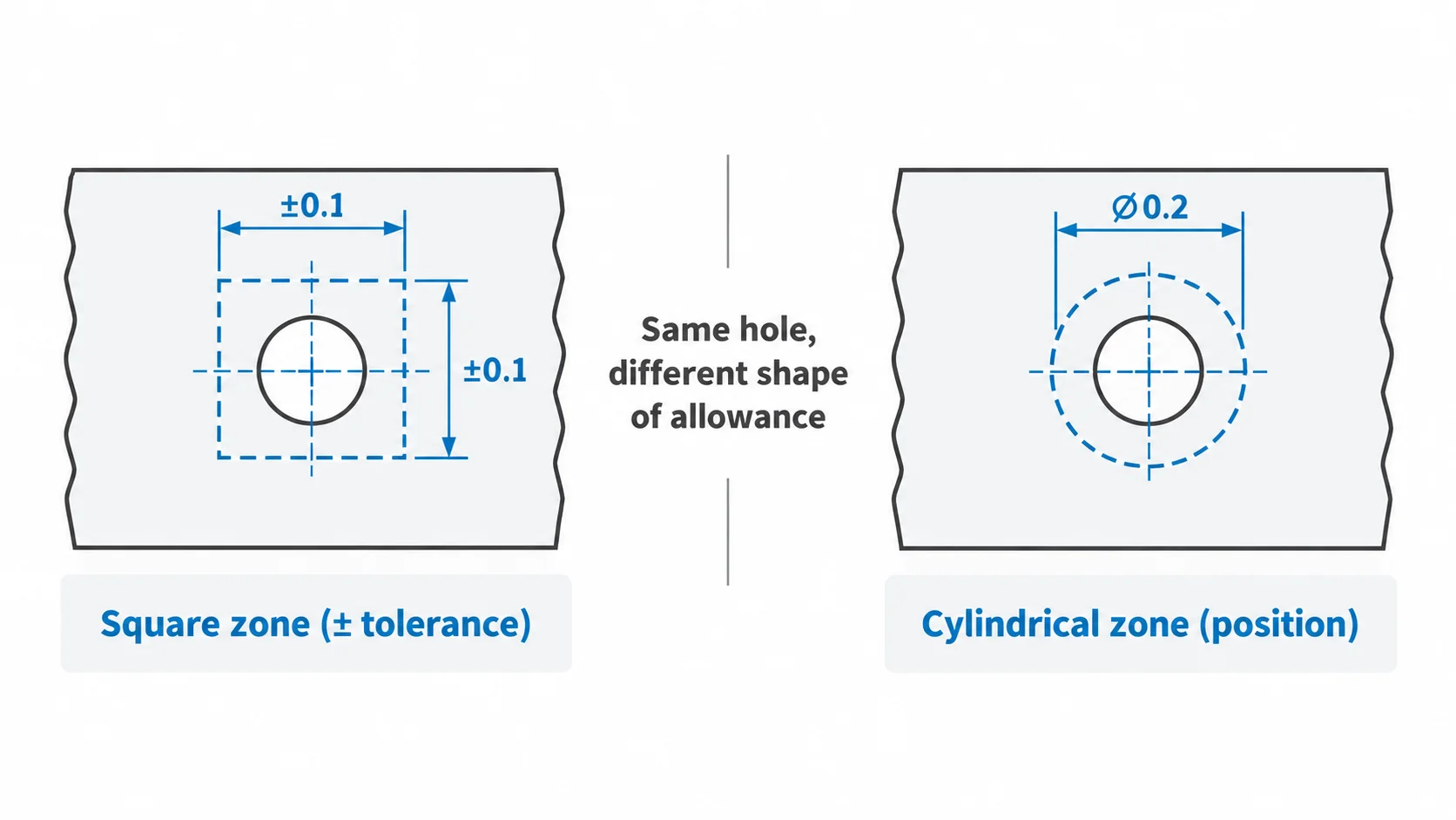
The difference between plus/minus tolerances and geometric tolerances is not only about how tight they are. It is about the shape of the space the feature is allowed to occupy.
A hole located with ± coordinate tolerances is allowed to move inside a square or rectangular zone. A hole controlled by position is allowed to move inside a circular or cylindrical tolerance zone. For a round fastener, the circular zone matches the way the joint actually behaves.
A common rule of thumb is that a bilateral ±0.1 mm tolerance in both axes is roughly comparable to a ∅0.2 mm position tolerance for a round feature. The zones are not identical: the square zone allows slightly more deviation in the diagonal direction, while the cylindrical position zone concentrates the allowance where the fastener needs it.
True position deviation is calculated as:
True Position = 2 × √(Δx² + Δy²)
where Δx and Δy are the measured deviations from the basic (theoretically exact) location. If the calculated value is smaller than the stated tolerance, the feature is acceptable.
This is why position tolerances are so common on bolt-hole patterns, dowel holes, and bearing locations, where function depends on the relationship between features rather than on a simple coordinate distance.
How Different GD&T Controls Affect CNC Machining
Different geometric tolerances create different manufacturing challenges.
| GD&T Control | What It Controls | Typical CNC Manufacturing Impact |
|---|---|---|
| Flatness | Entire surface | May require finish milling, grinding, or controlled clamping |
| Straightness | Line or axis | Affects turning, guide surfaces, shafts |
| Circularity | Round cross-section | Requires stable turning or precision finishing |
| Cylindricity | Entire cylindrical surface | May require precision turning or grinding |
| Parallelism | Orientation to datum | Requires reliable datum setup |
| Perpendicularity | 90° orientation | Often requires machining referenced faces in controlled setups |
| Position | Feature location | Requires accurate hole patterns, fixturing, and inspection |
| Surface Profile | 3D surface geometry | May require 5-axis machining and CMM inspection |
| Circular Runout | Rotation at one section | Often requires same-setup turning |
| Total Runout | Entire rotating surface | Requires tighter axis control and more demanding inspection |
The tighter these requirements become, the more sensitive the manufacturing process becomes to fixturing, tool deflection, temperature, machine capability, and inspection method.
How Flatness Affects CNC Machining
Flatness controls how much an entire surface can deviate from a perfect plane.
It does not require a datum because it controls the surface itself.
For ordinary machined surfaces, standard face milling may be enough.
However, a much tighter flatness tolerance can require:
- Additional finishing passes
- Reduced cutting depth
- Better workholding
- Lower clamping distortion
- Stress relief before final machining
- Grinding or lapping
- More detailed inspection
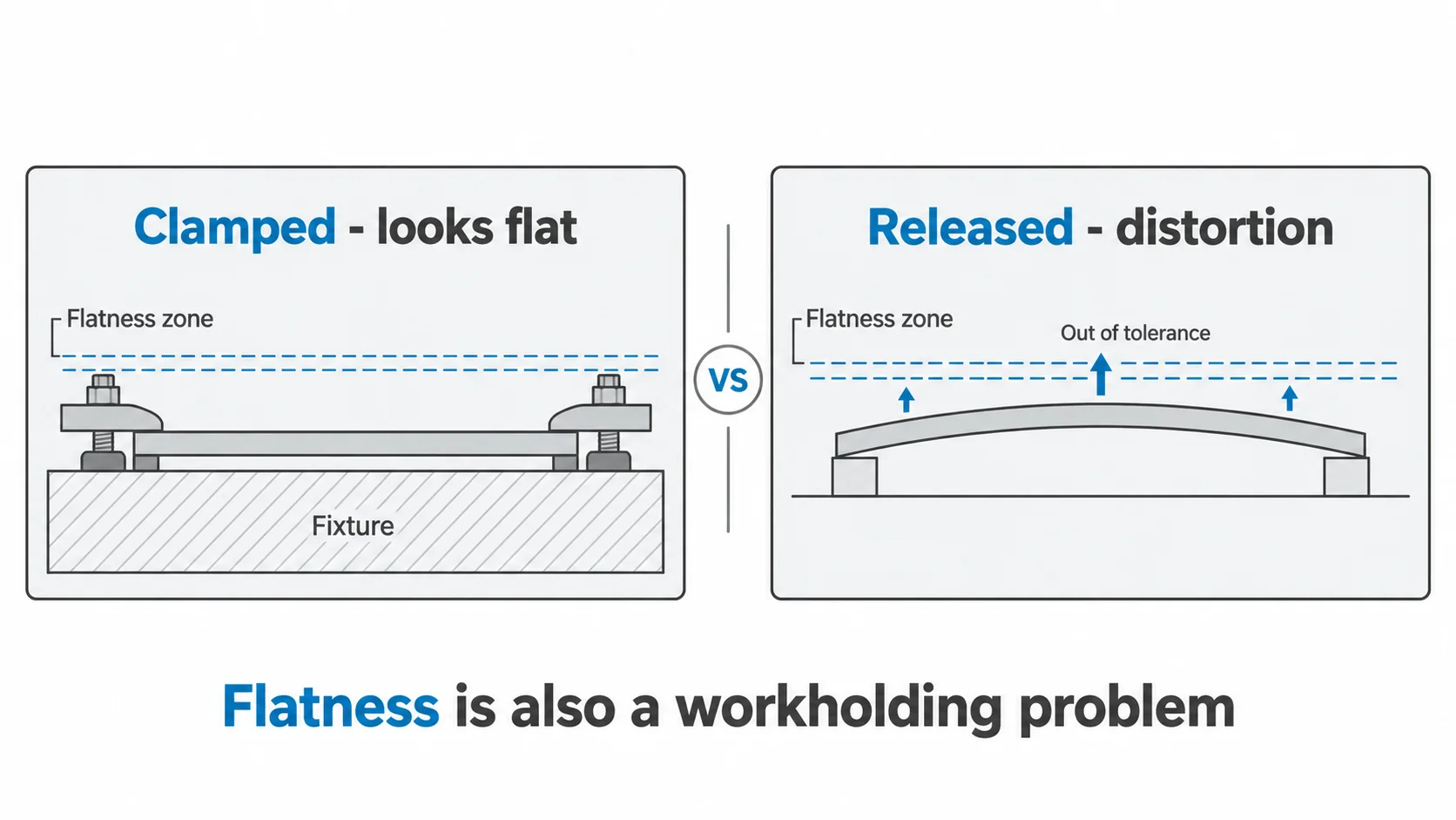
One common problem occurs when a thin plate is clamped too tightly.
The surface may appear flat while clamped, but after the fixture is released, internal stress or clamping deformation can cause the part to move.
Therefore, tight flatness is not only a machine accuracy problem. It is also a workholding and material stability problem.
For large flat features, CNC milling strategy and fixture design can have a major effect on the final result.
How Perpendicularity Affects Setup Planning
Perpendicularity controls how close a feature is to 90 degrees relative to a datum.
For example, a bore may need to remain perpendicular to a mounting face.
If the mounting face is Datum A, then the machining process should ideally establish that surface first.
The bore can then be machined while maintaining a known relationship to Datum A.
If the features are machined in unrelated setups, fixture variation and datum transfer error can accumulate.
This is why perpendicularity requirements often influence the order in which features are machined.
A common strategy is:
Machine Datum Surface → Establish Fixture Reference → Machine Perpendicular Feature
Reducing unnecessary setup changes can improve both accuracy and repeatability.
How Position Tolerance Affects Hole Machining
Position is one of the most common GD&T controls on CNC machined parts.
It is frequently used for:
- Bolt-hole patterns
- Dowel holes
- Bearing locations
- Threaded holes
- Precision locating features
Unlike a simple ± coordinate tolerance, true position controls the feature relative to theoretically exact basic dimensions and referenced datums.
A tight position requirement can affect:
- CNC machine accuracy
- Fixture repeatability
- Tool selection
- Hole-making sequence
- Datum alignment
- Inspection method
For example, a loose clearance-hole pattern may be easily produced by standard drilling.
A tight dowel-hole pattern may require:
Drilling → Semi-finishing → Reaming or Boring → CMM Inspection
The machining process should match the functional requirement rather than applying the same process to every hole.
How Runout Affects CNC Turning
Runout is especially important for turned components.
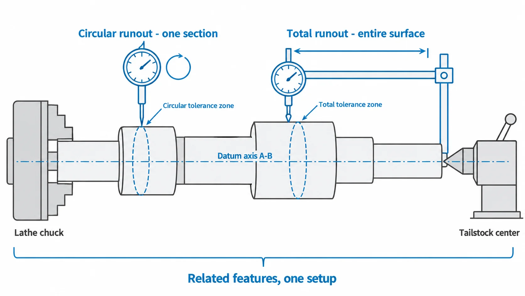
Circular runout controls variation at an individual cross-section as the part rotates around a datum axis.
Total runout controls the entire rotating surface.
Typical parts include:
- Shafts
- Bearing journals
- Spindles
- Rotors
- Pulleys
- Sealing diameters
Tight runout usually means related cylindrical features should be machined without removing the part from the setup whenever possible.
For example:
Journal A → Journal B → Shoulder Face
machined in one setup will usually maintain a better common axis than machining each feature in separate setups.
This is one reason CNC turning and mill-turn machining are useful for components with demanding concentric relationships.
How Surface Profile Affects 5-Axis Machining
Profile of a surface is particularly useful for complex 3D geometry.
It can simultaneously control the shape and, when datums are referenced, the location and orientation of an entire surface.
Typical applications include:
- Aerospace housings
- Curved structural parts
- Turbine-related geometry
- Complex automotive parts
- Medical components
- Multi-surface CNC housings
A tight surface profile tolerance can require:
- Accurate 3D toolpaths
- Controlled tool orientation
- Reduced setup changes
- Stable workholding
- Precise CAM programming
- CMM or 3D inspection
Complex surfaces are often good candidates for 5-axis CNC machining because multiple features can be machined in a single setup while maintaining their geometric relationship.
How GD&T Affects CNC Setup and Fixturing
GD&T often determines how the workpiece should be located in the machine.
A datum system defines the reference framework for the part.
A typical machining sequence may be:
Datum A → Datum B → Datum C → Critical Features
Datum A normally establishes the primary orientation.
Datum B removes additional degrees of freedom.
Datum C establishes the final rotational or lateral location.
This relationship is important because poor datum selection can create unnecessary setup complexity.
For example, if Datum A is difficult to fixture or is only created late in the machining process, the manufacturer may need additional operations to reproduce the drawing reference accurately.
Good DFM practice is to select datums that are:
- Functionally meaningful
- Stable
- Accessible
- Easy to fixture
- Easy to inspect
This helps align design intent with manufacturing reality. The 3-2-1 locating principle works the same way: primary datum constrains three degrees of freedom, secondary constrains two, and tertiary constrains the last one.
How GD&T Affects CNC Machining Cost
GD&T can significantly affect part price.
The biggest cost increase usually comes not from the presence of GD&T itself, but from unnecessarily tight geometric tolerances.
A tighter requirement can increase:
- Machine time
- Number of setups
- Fixture complexity
- Tooling requirements
- Finishing operations
- Inspection time
- Scrap risk
- Rework risk
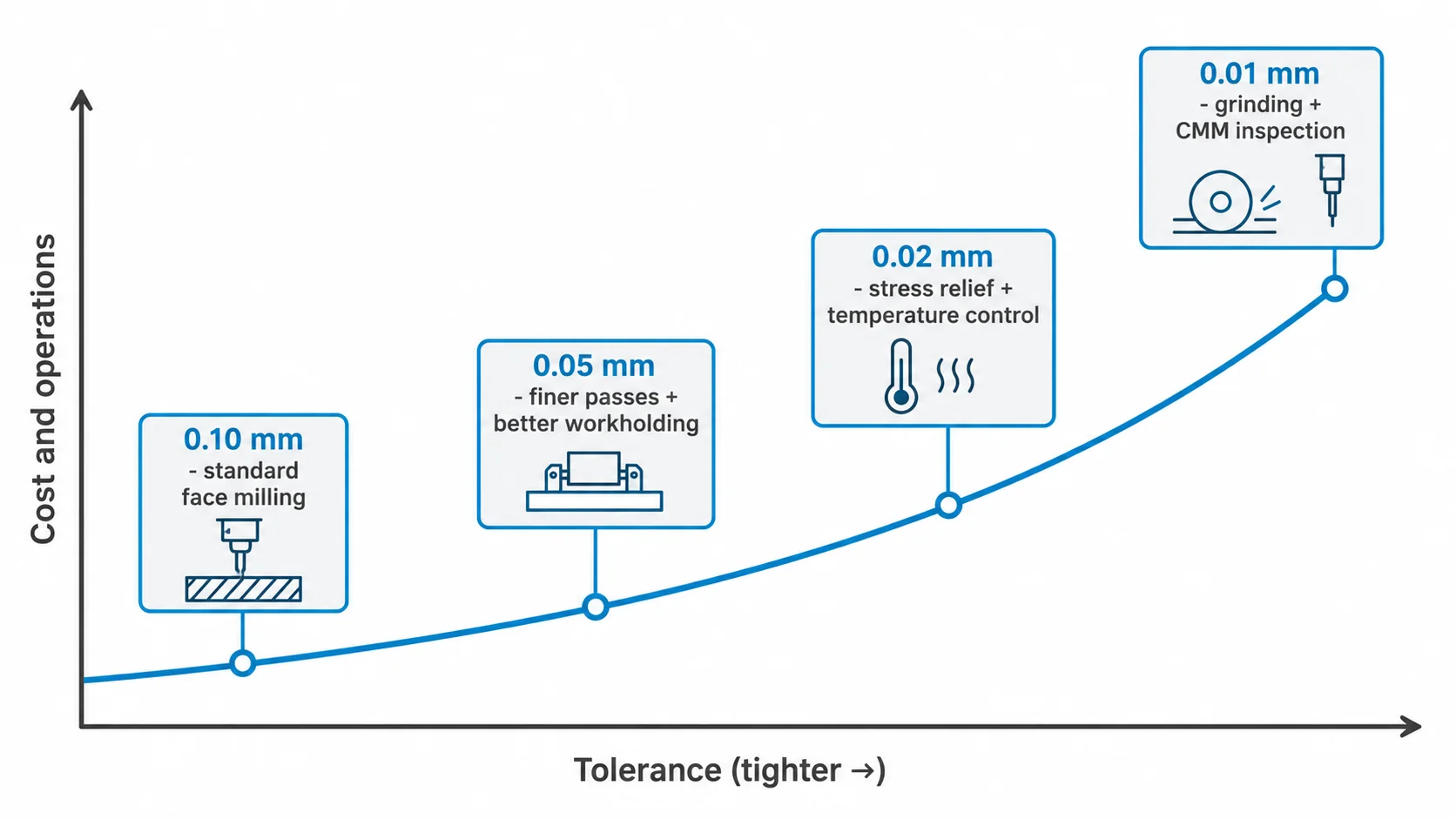
The table below shows how a flatness requirement on a moderate-size machined face typically escalates the process:
| Flatness Requirement | What It Usually Adds | Cost Impact |
|---|---|---|
| 0.10 mm | Standard face milling and normal clamping | Baseline |
| 0.05 mm | Finer finishing passes, better workholding | Moderate increase |
| 0.02 mm | Stress relief, controlled clamping, temperature control | Significant increase |
| 0.01 mm or tighter | Grinding or lapping, dedicated fixturing, CMM verification | High increase |
The same principle applies to position, runout, cylindricity, perpendicularity, and surface profile.
The question should therefore be:
How much geometric accuracy does the function actually require?
not:
What is the tightest tolerance we can place on the drawing?
Achievable Tolerances by CNC Process
When a drawing tolerance is reviewed, the first question is whether the process can hold it economically. The values below are typical production references for moderate-size steel or aluminum parts. Actual capability depends on part size, material, geometry, tooling, fixturing, and inspection method.
| Process | Typical Achievable Tolerance | Typical Surface Finish (Ra) | Notes |
|---|---|---|---|
| CNC milling (standard) | ±0.05 mm | 1.6–3.2 µm | Suitable for most pocket, profile, and hole features |
| CNC milling (precision) | ±0.01 mm | 0.8–1.6 µm | Requires stable fixturing, finishing passes, and careful inspection |
| CNC turning | ±0.025 mm | 0.8–1.6 µm | Diameters, bores, and faces on rotational parts |
| CNC grinding | ±0.005 mm | 0.2–0.8 µm | Hardened parts and tight geometric requirements |
| EDM / wire EDM | ±0.005 mm | 0.4–1.6 µm | Hard materials, sharp internal corners, thin features |
| Honing | ±0.002 mm | 0.1–0.4 µm | Cylinder bores requiring roundness and consistent finish |
If a drawing calls for a tolerance that is beyond the economical range of the intended process, the feature usually has to be moved to a finer process, which changes both cost and lead time.
Tighter GD&T Does Not Always Mean a Better Part
Over-tolerancing is a common source of unnecessary manufacturing cost.
If a non-critical surface receives a very tight flatness tolerance, the manufacturer still has to produce and inspect that requirement even if it has no effect on assembly or performance.
Likewise, a decorative hole pattern may not need the same true position tolerance as precision dowel holes.
Good drawings differentiate between:
Functional features
and
Non-critical features
Tight tolerances should be reserved for relationships that affect:
- Assembly
- Movement
- Sealing
- Bearing alignment
- Load transfer
- Interchangeability
- Product performance
This allows the manufacturer to focus precision where it actually matters.
MMC, LMC, and Bonus Tolerance
Material condition modifiers can provide additional manufacturing flexibility.
MMC — Maximum Material Condition
For an internal feature such as a hole, MMC occurs at the smallest permitted hole diameter.
LMC — Least Material Condition
For a hole, LMC occurs at the largest permitted diameter.
When MMC is applied to certain geometric controls such as position, additional bonus tolerance may become available as the actual feature size moves away from MMC.
A simple example:
- A hole is specified as ∅10 +0.2/0 with a position tolerance of ∅0.2 at MMC
- At MMC (10.0 mm), the available position tolerance is ∅0.2 mm
- If the hole is produced at 10.1 mm, the bonus tolerance is 0.1 mm, so the available position tolerance becomes ∅0.3 mm
- If the hole is produced at 10.2 mm, the available position tolerance becomes ∅0.4 mm
Bonus tolerance applies to the geometric tolerance when the modifier follows the tolerance in the feature control frame. Modifiers on datum references work differently and should not be treated as bonus tolerance.
Used correctly, MMC can:
- Protect functional assembly
- Reduce unnecessary machining precision
- Increase manufacturing yield
- Lower inspection rejection risk
It is a good example of how GD&T can reduce cost when used correctly rather than simply making tolerances more restrictive.
How Are GD&T Requirements Inspected?
Different GD&T controls require different inspection methods.
Common equipment includes:
- Coordinate Measuring Machine (CMM)
- Dial indicator
- Surface plate
- Height gauge
- Bore gauge
- Roundness tester
- Optical measuring equipment
A simple flatness check may be possible using a surface plate and indicator.
A complex 3D profile may require CMM inspection.
Position tolerances on multi-feature hole patterns are also commonly verified using a CMM.
Inspection planning should therefore be considered during the quoting stage.
A drawing with complex geometric tolerances may require more inspection time even if the machining itself is straightforward.
At YUANYI Precision Manufacturing, dimensional inspection can be supported according to drawing requirements, including dimensional reports, material certificates, and other documentation depending on the project. You can learn more about our inspection process on our Quality Assurance page.
GD&T Examples on CNC Machined Parts
Understanding GD&T is easier when connected to real component types.
Precision Plate
Typical requirements:
- Flatness on mounting face
- Position on hole pattern
- Perpendicularity on side surfaces
The main challenge is controlling workpiece distortion while maintaining hole relationships to the primary datum.
Precision Shaft
Typical requirements:
- Circular runout
- Total runout
- Cylindricity
- Perpendicularity of shoulders
The most effective strategy is often to machine related rotational features in one setup.
Bearing Housing
Typical requirements:
- Position of bearing bore
- Perpendicularity to mounting face
- Cylindricity of bore
- Flatness of mating surface
A combination of CNC milling and precision boring may be required.
5-Axis Housing
Typical requirements:
- Surface profile
- Position of multi-directional holes
- Perpendicularity
- Datum-referenced features
Reducing setup changes can be critical because every re-fixturing operation introduces potential datum transfer error.
Common GD&T Mistakes That Increase Machining Cost
Several drawing mistakes frequently create avoidable manufacturing difficulty.
Applying tight tolerances everywhere
Not every surface requires high geometric precision.
Selecting impractical datums
A datum that is difficult to access, fixture, or inspect can increase setup complexity.
Using separate setups for features that need a common axis
This can make runout and concentric relationships harder to maintain.
Applying tight position to clearance holes unnecessarily
Clearance holes often allow more positional variation than locating holes.
Ignoring material movement
Thin parts, long parts, and heat-treated components can distort after machining.
Using GD&T without defining the functional requirement
A drawing should describe how the part must function, not simply use more symbols.
Using outdated controls without checking the drawing standard
Older drawings may still show concentricity or symmetry, which ASME Y14.5-2018 removed. Confirm which standard and edition applies before quoting or inspecting.
How to Make a CNC Drawing Easier to Manufacture
A good CNC drawing should communicate function clearly without adding unnecessary restrictions.
Before releasing a drawing, consider:
- Which surfaces actually establish the assembly datum?
- Which holes are clearance holes and which are locating holes?
- Does this flatness requirement affect sealing or assembly?
- Does the shaft truly require tight total runout?
- Can related features be machined in one setup?
- Is CMM inspection required?
- Can MMC provide functional tolerance flexibility?
- Are critical tolerances tighter than necessary?
Early DFM review can often identify these issues before production, and it is the cheapest point in the project to change a tolerance.
Final Thoughts
GD&T is not only a drawing language. It is a manufacturing tool.
When geometric tolerances are defined correctly, they help CNC programmers, machinists, and inspectors understand which relationships actually matter to the finished part.
When they are applied unnecessarily tightly, they can increase setup complexity, inspection time, scrap risk, and production cost.
The best GD&T strategy is therefore to connect every geometric tolerance to a functional requirement.
For CNC parts, that usually means considering:
Datum strategy → Machining setup → Geometric tolerance → Inspection method → Functional requirement
At YUANYI Precision Manufacturing, we review drawings, tolerances, materials, and critical features before production to identify machining risks and support practical manufacturing decisions.
Have a CNC drawing with complex GD&T requirements? Send us your drawing for a DFM review and machining quotation.
Frequently Asked Questions
Not automatically. Proper GD&T can actually reduce cost by allowing acceptable geometric variation while protecting functional requirements. Cost usually increases when tolerances are unnecessarily tight or require additional setups, finishing, and inspection.
Plus/minus tolerances control size and distance within a square or rectangular zone. GD&T controls the shape, orientation, location, and runout of features, usually within a circular, cylindrical, or defined tolerance zone. A common rule of thumb is that a bilateral ±0.1 mm tolerance is roughly comparable to a ⌀0.2 mm position tolerance for a round feature.
No. Many parts are fully defined with plus/minus tolerances. GD&T is used when the function of the part depends on geometry or on the relationship between features, such as hole patterns, bearing seats, sealing faces, or rotating assemblies.
There is no single hardest tolerance. Tight total runout, cylindricity, surface profile, and position can all become difficult depending on part size, geometry, material, and datum structure.
No. Flatness is a form control and applies directly to the controlled surface without referencing a datum.
Position commonly references datums when controlling a feature relative to the rest of a part. The exact requirement depends on how the feature is defined.
Yes. CMM inspection is widely used for position, profile, orientation, and other geometric controls, especially on complex CNC machined parts.
Runout controls how much a rotating surface varies relative to a datum axis. Excessive runout can affect bearings, seals, vibration, and rotating assemblies.
ASME Y14.5 and ISO 1101 are the two most common systems. The important points are to state the standard and edition on the drawing, and to apply it consistently. ASME Y14.5-2018 removed concentricity and symmetry, so legacy drawings should be checked before production.
Yes. Correct datum selection, realistic tolerances, and the use of modifiers such as MMC can reduce unnecessary machining and inspection requirements while maintaining functional performance.



