

Deep hole drilling is a machining process used to produce holes with a high depth-to-diameter ratio. These holes are more difficult to machine than shallow holes because cutting tools must maintain alignment while removing chips and delivering coolant deep inside the workpiece.
A hole with a depth-to-diameter ratio of 10:1 or greater often requires additional process planning, although the exact threshold depends on the material, tooling, machine, and tolerance requirements.
Common deep hole drilling methods include peck drilling, through-coolant drilling, gun drilling, and BTA drilling.
This guide explains how hole depth affects machining difficulty, which processes to consider, and how engineers can design deep holes that are easier to manufacture.
What Is Deep Hole Drilling?
Deep hole drilling refers to machining holes whose depth is large relative to their diameter.
The main measurement used to evaluate machining difficulty is the depth-to-diameter ratio (L/D).
L/D = Hole Depth ÷ Hole Diameter
For example, a 6 mm diameter hole drilled to a depth of 120 mm has a ratio of:
120 ÷ 6 = 20:1 (20×D)
A 20×D hole presents greater challenges than a 3×D hole of the same diameter because the cutting tool must operate deeper inside the material.
As hole depth increases, several problems become more significant:
- Chip evacuation becomes more difficult.
- Coolant may struggle to reach the cutting edge.
- Long drills become more susceptible to deflection.
- Hole straightness becomes harder to control.
- Tool breakage can become more costly.
Deep holes are commonly found in hydraulic manifolds, industrial shafts, cooling channels, molds, and mechanical components requiring internal fluid passages.
Deep Hole Drilling Depth-to-Diameter Ratio Chart
The depth-to-diameter ratio is a useful starting point for selecting a drilling process.
The following chart uses a 6 mm diameter hole to illustrate how drilling depth changes machining requirements.
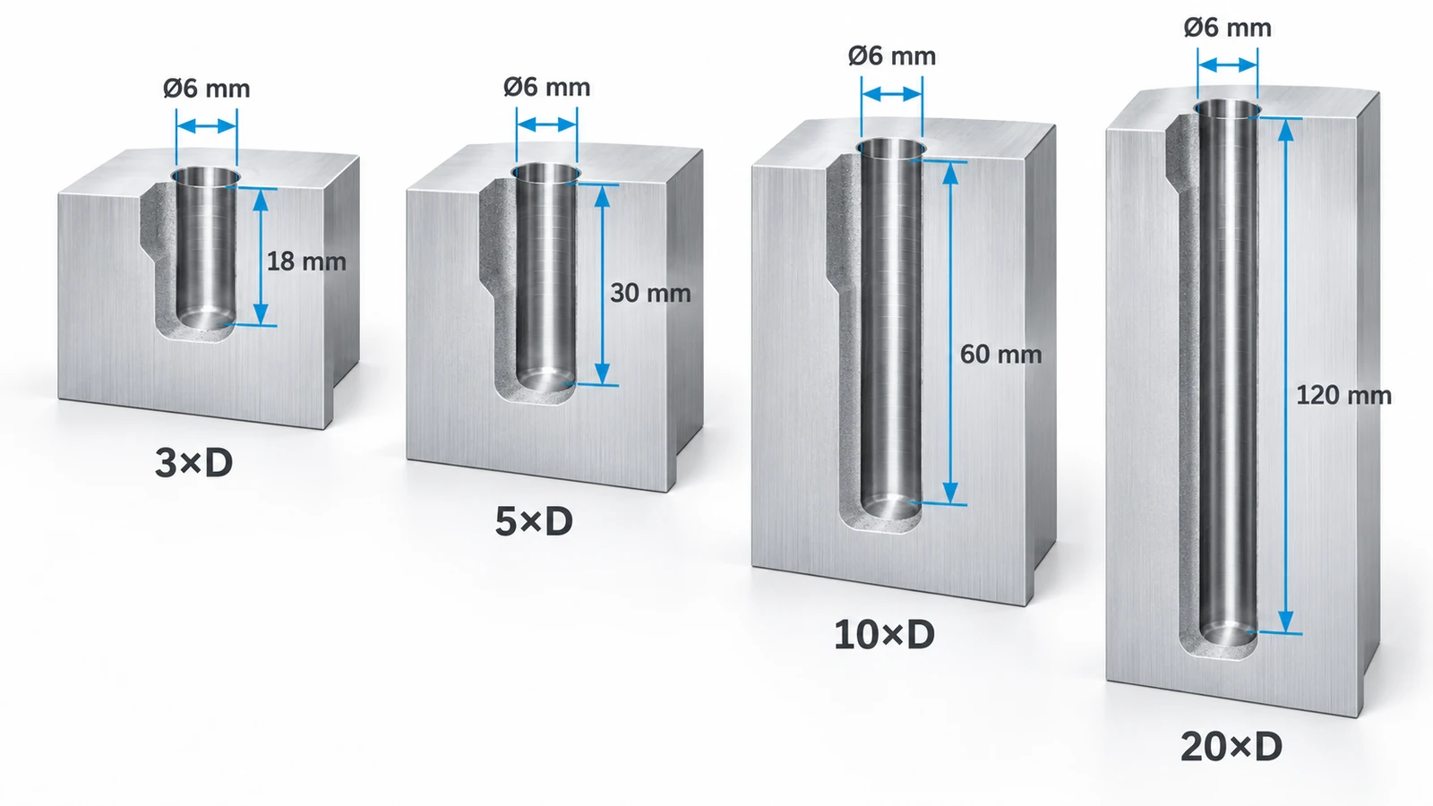
| L/D Ratio | Hole Depth (Ø6 mm) | General Machining Considerations |
|---|---|---|
| 3×D | 18 mm | Usually suitable for conventional drilling |
| 5×D | 30 mm | Chip removal and drill length become more important |
| 10×D | 60 mm | Evaluate extended-length tooling, guidance, and coolant delivery |
| 15×D | 90 mm | Greater attention to tool stability and hole straightness |
| 20×D | 120 mm | Consider specialized long drills or gun drilling |
| 30×D | 180 mm | Requires careful evaluation of dedicated deep-hole tooling and equipment |
These are general process-planning guidelines, not fixed machining limits. Actual capabilities depend on the specific drill, material, machine, coolant system, and required hole quality.
Why Does L/D Ratio Matter?
Two holes can have the same depth but very different machining difficulty.
For example:
- Ø20 × 100 mm = 5×D
- Ø5 × 100 mm = 20×D
Although both holes are 100 mm deep, the smaller hole has a much higher depth-to-diameter ratio.
The Ø5 mm hole requires a longer, more slender cutting tool relative to its diameter, which increases the importance of tool guidance, rigidity, and chip evacuation.
However, a low L/D ratio does not automatically guarantee easy machining. Difficult materials, angled entry surfaces, tight positional tolerances, or poor tool access can also make relatively shallow holes challenging.
Common Deep Hole Drilling Methods
Different machining methods are used depending on the hole diameter, depth, material, and production requirements.
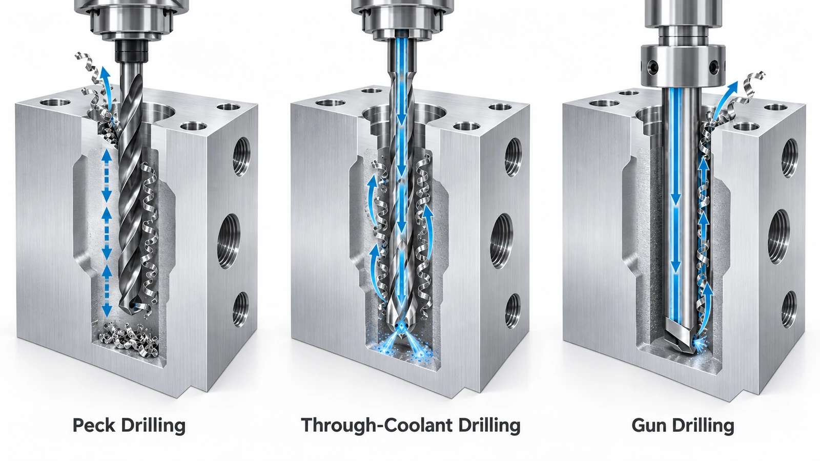
Peck drilling is a machining cycle, through-coolant drilling describes a coolant delivery approach, and gun drilling and BTA drilling are dedicated deep-hole machining processes.
They should not be treated as four identical categories.
1. Peck Drilling
Peck drilling uses repeated cutting advances, often with partial or full tool retraction, to manage chip formation and evacuation.
Instead of drilling the entire hole continuously, the drill advances incrementally.
Depending on the cycle, it may retract slightly to break chips or withdraw farther to help clear them.
Best suited for: Applications where conventional drilling requires periodic chip clearing.
Main limitation: Repeated retractions can increase cycle time and do not eliminate the risk of hole deviation.
Peck drilling should not automatically be used with every long drill. Some high-performance deep-hole drills are specifically designed for continuous feed with internal coolant.
2. Through-Coolant Drilling
Through-coolant drills deliver cutting fluid through internal channels directly to the cutting zone.
This improves heat removal and helps transport chips out of the hole.
Specialized solid-carbide drills are available for high depth-to-diameter ratios, including certain 20×D and 30×D applications.
Some long-drill systems require a accurately machined pilot hole before the deep-hole tool enters at its operating speed.
Best suited for: Deep holes where appropriate long drills, coolant pressure, and machine capabilities are available.
Main limitation: Performance depends on the specific tooling system and the machine’s ability to deliver adequate coolant pressure and flow.
3. Gun Drilling
Gun drilling is a specialized deep-hole machining process commonly used for long, relatively small-diameter holes.
A conventional single-lip gun drill has an internal coolant passage and an external chip evacuation channel.
Coolant reaches the cutting area through the tool, while chips and fluid return along the external channel.
Guide pads support the tool against the machined hole wall, helping maintain stability.
Gun drilling is used for applications such as hydraulic passages, precision shafts, molds, and other components with long internal holes.
However, gun drilling may require specialized equipment, guide arrangements, and high-pressure coolant systems.
4. BTA Drilling
BTA drilling is another specialized deep-hole machining method, often used for larger-diameter holes and demanding production applications.
In a conventional single-tube BTA system, coolant flows around the drill tube toward the cutting head, while chips return through the hollow center of the tube.
This internal chip evacuation system can be advantageous for larger holes and higher material-removal rates.
BTA drilling generally involves more specialized equipment than ordinary CNC drilling.
Deep Hole Drilling Method Comparison
| Method | Main Advantage | Important Limitation |
|---|---|---|
| Peck drilling | Helps manage chips using standard drilling equipment | Additional retractions and cycle time |
| Through-coolant drilling | Improves cooling and chip evacuation | Requires compatible tools and coolant capability |
| Gun drilling | Designed for high-L/D holes with guided cutting | Specialized tooling and setup |
| BTA drilling | Efficient chip evacuation for larger deep holes | Dedicated equipment and greater setup complexity |
The best process should be selected from the actual drawing requirements rather than the L/D ratio alone.
Common Deep Hole Drilling Challenges
Deep hole drilling can produce several dimensional and surface-quality problems if the cutting process is not properly controlled.
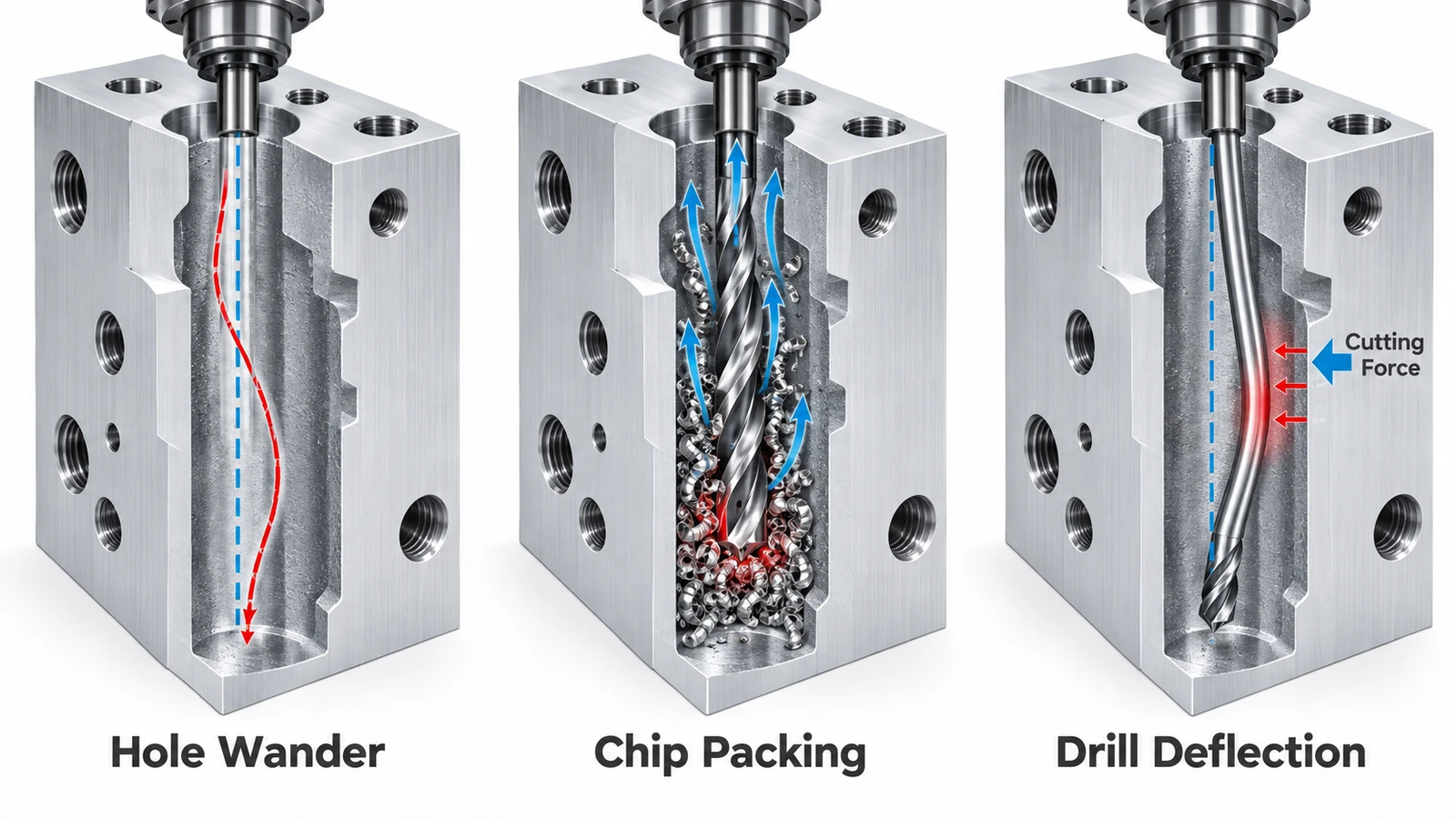
| Problem | Common Cause | Possible Solution |
|---|---|---|
| Hole wander | Tool deflection, poor guidance, uneven entry | Improve entry geometry, guidance, and tooling |
| Chip packing | Insufficient chip evacuation | Improve coolant flow and chip control |
| Drill breakage | Excessive loading, chip blockage, instability | Review parameters, tool geometry, and setup |
| Poor straightness | Entry error and cumulative tool deviation | Use suitable pilot and guidance strategies |
| Poor surface finish | Chip rubbing, vibration, tool wear | Improve chip evacuation and cutting stability |
| Hole diameter variation | Runout, wear, thermal effects | Control tooling, machining conditions, and inspection |
Hole Wander and Drill Deflection
Hole wander occurs when the drilled hole deviates from its intended path.
An initial positioning error or tool deflection can develop into a significant deviation farther into the workpiece.
This is particularly important for holes that must intersect another passage or remain accurately positioned relative to an external surface.
A properly prepared entry surface, appropriate pilot hole, and stable cutting tool can reduce the risk.
However, even specialized deep-hole tools do not guarantee perfect straightness.
Chip Packing and Tool Breakage
When chips cannot leave the hole efficiently, they may accumulate around the cutting edges.
Chip packing increases friction and heat, damages the machined surface, and can cause drill breakage.
The problem becomes more difficult as hole depth increases.
Effective coolant delivery, suitable chip formation, and the correct drilling strategy are essential.
Heat and Surface Quality
Heat generated at the cutting zone can accelerate tool wear and affect dimensional consistency.
Poor coolant access or chips rubbing against the hole wall may also damage the finished surface.
Different materials produce different chip forms. Aluminum can form long chips under certain conditions, while some stainless steels are difficult to break into manageable chips.
Tool geometry and cutting parameters should therefore be selected for the specific material.
Deep Hole Drilling Tolerances and Inspection
A deep hole may satisfy its specified diameter while still failing other dimensional requirements.
For this reason, deep-hole quality should be evaluated using several independent characteristics.
| Quality Requirement | What It Controls |
|---|---|
| Hole diameter | Size of the finished opening |
| Hole position | Location relative to drawing datums |
| Straightness | Deviation of the hole axis along its length |
| Surface roughness | Condition of the internal machined surface |
| Depth | Required axial extent of the hole |
| Intersection accuracy | Alignment with connecting holes or channels |
Diameter and Straightness Are Different
A deep hole can have an acceptable diameter but a curved or displaced centerline.
For example, a Ø6 mm hole drilled 120 mm deep may satisfy its diameter tolerance while deviating from the intended axis.
If the hole must connect with another internal passage, this deviation could prevent the intended connection.
The drawing should specify which geometric requirements are functionally important.
How Are Deep Holes Inspected?
Inspection methods depend on hole diameter, depth, accessibility, and tolerance.
Common approaches include:
- Pin gauges or suitable bore gauges for accessible diameters.
- Depth gauges or probing for hole depth.
- Coordinate measuring methods for accessible entry and exit positions.
- Specialized bore inspection or non-destructive methods for inaccessible internal geometry.
Measuring the hole entrance alone does not verify the straightness of the entire bore.
For demanding applications, the inspection method should be agreed upon before manufacturing.
CNC Deep Hole Design Guidelines
Good design can significantly reduce the difficulty and cost of deep-hole machining.
The following guidelines are especially useful when preparing CAD models and engineering drawings.
1. Keep Hole Depth as Short as Functionally Possible
Avoid specifying unnecessarily deep holes.
For a Ø6 mm hole, reducing the required depth from 120 mm to 60 mm changes the depth-to-diameter ratio from 20×D to 10×D.
This may expand the available tooling and process options.
However, the exact cost benefit depends on the equipment and quality requirements.
2. Provide a Suitable Entry Surface
A flat surface perpendicular to the drill axis is generally easier for stable tool entry than an angled or interrupted surface.
When the entry surface is inclined, the tool may experience uneven loading before becoming fully engaged.
A spotfaced entry or another appropriately prepared starting feature may be useful.
3. Allow for Tool Guidance
Very long drills may require pilot holes, guide bushings, or other support arrangements.
A pilot hole must have the diameter, depth, and alignment required by the selected tool system.
An arbitrary pilot hole may provide poor guidance and increase the risk of tool failure.
4. Specify Only Necessary Tolerances
Tight diameter and positional tolerances can increase machining complexity and inspection costs.
Do not apply demanding tolerances unless they are required by the function of the component.
If the hole only carries fluid, its geometric requirements may differ from those of a precision guide hole or locating feature.
5. Consider Blind-Hole Bottom Geometry
Blind holes need special attention because the drill point creates a conical bottom.
The usable cylindrical depth is not necessarily the same as the distance to the drill tip.
Specify whether the required depth refers to full-diameter depth or drill-tip depth.
If a flat-bottom hole is essential, a separate finishing operation may be needed.
6. Review Hole Intersections and Wall Thickness
Intersecting internal passages can create interrupted cutting conditions, burrs, and difficult-to-clean areas.
Deep holes placed close to exterior surfaces can also leave thin walls.
Designers should check minimum wall thickness, hole intersections, and access for deburring or cleaning.
For demanding applications, it is useful to request a manufacturability review before finalizing the drawing.
Deep Hole Drilling Cost and DFM Example
Deep-hole machining cost is affected by more than the hole diameter and depth.
Important factors include:
- Depth-to-diameter ratio.
- Workpiece material and hardness.
- Available cutting tools and equipment.
- Required hole straightness and position.
- Blind or through-hole geometry.
- Coolant delivery and chip removal requirements.
- Production quantity and inspection needs.
Engineering Example: Ø6 × 120 mm Blind Hole
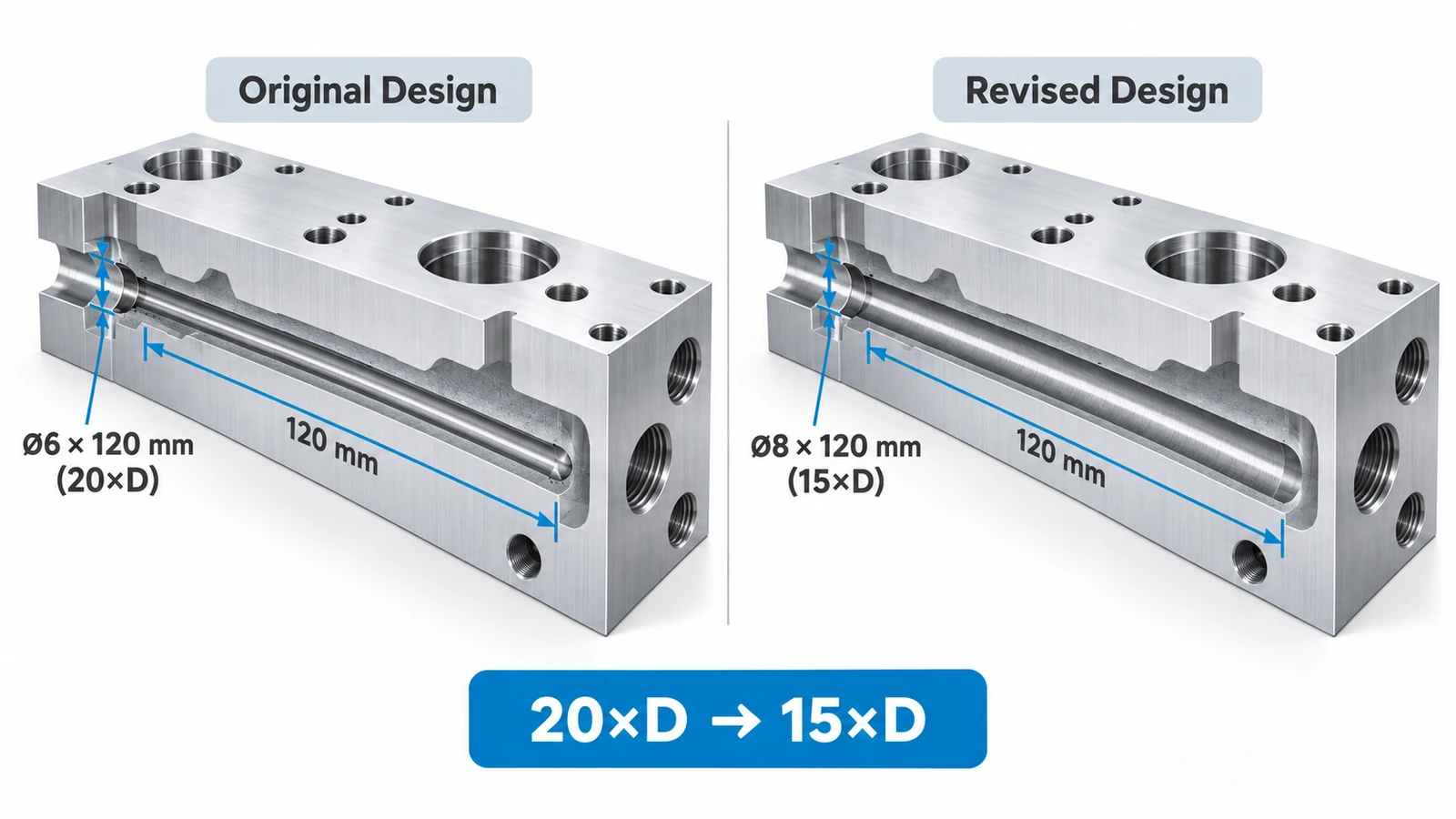
Consider a custom aluminum component requiring a Ø6 mm blind hole with a cylindrical depth of 120 mm.
The depth-to-diameter ratio is:
120 ÷ 6 = 20×D
At this ratio, the manufacturer should evaluate more than an ordinary drilling cycle.
Step 1: Review the Drawing
Confirm whether 120 mm refers to the full-diameter depth or the drill-tip depth.
Also identify the required hole diameter tolerance, positional requirements, and connection to any internal channels.
Step 2: Evaluate the Cutting Method
Possible options include a suitable long through-coolant carbide drill or a dedicated gun-drilling process.
The final choice depends on equipment capability, workpiece geometry, and hole-quality requirements.
A high-L/D carbide drill may require a precision pilot hole and a tool-specific entry procedure.
Step 3: Control Chip Evacuation
At 120 mm depth, efficient chip removal is essential.
Coolant delivery, chip formation, and tool compatibility must be considered together.
Simply increasing coolant pressure or adding repeated peck cycles is not a universal solution.
Step 4: Evaluate Hole Accuracy
A successful drilling operation must meet the specified hole diameter and any functional straightness or positional requirements.
If the hole must intersect another channel, the permissible deviation should be reviewed before machining.
Step 5: Consider DFM Improvements
If the function allows, possible design changes include:
- Reducing the required hole depth.
- Increasing the hole diameter.
- Modifying the entry surface.
- Relaxing unnecessary tolerances.
- Redesigning the internal passage layout.
For example, increasing the hole diameter from Ø6 mm to Ø8 mm while keeping the depth at 120 mm changes the ratio from 20×D to 15×D.
That may make additional drilling options practical, although the final process must still be verified.
This is an illustrative engineering example, not a claim that every 20×D hole can be produced using conventional CNC equipment.
Conclusion
Deep hole drilling becomes more demanding as the depth-to-diameter ratio increases, particularly when hole straightness, chip evacuation, and positional accuracy are important.
Peck drilling, through-coolant drilling, gun drilling, and BTA drilling provide different ways to address these challenges, but no single method is suitable for every deep hole.
Engineers can improve manufacturability by selecting reasonable hole depths, providing suitable entry geometry, controlling tolerances, and reviewing tooling and inspection requirements early in the design process.
Need custom CNC-machined components with precision holes or complex internal features?
YUANYI provides CNC milling, turning, and manufacturability review services for custom metal and plastic parts. Send us your CAD files or engineering drawings to discuss your project’s machining requirements and request a quotation.
Frequently Asked Questions
There is no single universal threshold for every operation. Holes around 10×D or greater often require additional deep-hole process planning, although shorter holes can also be difficult when material, geometry, or tolerance requirements are demanding.
Potentially, yes. Some CNC machines equipped with appropriate long drills, high-pressure through-coolant systems, and suitable guidance can machine 20×D holes. Feasibility must be verified for the specific machine, tool, material, and drawing requirements.
Gun drilling is designed for high-depth-ratio applications and can provide better process stability and straightness in suitable conditions. However, accuracy depends on the tool, setup, material, and equipment. It should not be assumed to outperform every conventional drilling operation.
Conventional drilling normally leaves a conical bottom. A flat-bottom requirement may need additional machining with an appropriate finishing tool or another manufacturing method.
No. Some extended-length carbide drills are designed for continuous cutting with internal coolant and a specified pilot-hole procedure. Always follow the selected tool manufacturer’s instructions.



