

CNC undercuts are recessed features that cannot be fully reached by a standard end mill from an available machining direction. Common examples include T-slots, dovetail grooves, and hidden recesses beneath overhanging surfaces. These features often require specialized cutting tools, additional setups, or alternative machining methods.
Not every undercut requires 5-axis machining. Many can be produced on a 3-axis CNC mill using T-slot, dovetail, or lollipop cutters. The main challenges are tool access, cutter clearance, rigidity, and chip evacuation.
This guide explains common CNC undercut types, suitable cutting tools, machining methods, and practical design guidelines for reducing manufacturing difficulty and cost.
What Is an Undercut in CNC Machining?
An undercut is a recessed geometric feature in which part of the material lies behind an overhanging surface or inside a region that a conventional end mill cannot directly access.
For example, a standard end mill can machine an open rectangular slot because its cutting edges can reach the slot walls and bottom from above.
A T-slot is different. Its internal cavity is wider than its opening, creating material overhangs on both sides. A standard end mill inserted through the narrow opening cannot machine the wider recessed areas without colliding with the surrounding material.
A T-slot cutter, however, has a larger cutting head connected to a narrower neck. After entering a prepared opening, the cutter can remove material beneath the overhanging surfaces.
Tool access is the key distinction. A feature that appears hidden from one direction may become accessible after rotating or repositioning the workpiece.
If a standard end mill can fully machine the feature from another practical setup direction, the design may not require a dedicated undercut cutter.
The most difficult undercuts are those that remain inaccessible even after changing the machining orientation.
Common Types of CNC Undercuts
Different undercut geometries require different machining strategies. The most suitable process depends on the feature shape, location, and intended function.
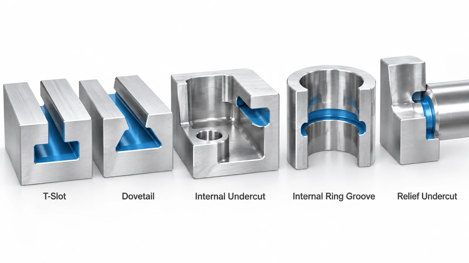
| Undercut Type | Geometry | Typical Tool | Common Application |
|---|---|---|---|
| T-Slot | Narrow entrance with a wider internal channel | T-slot cutter | Machine tables and fixture plates |
| Dovetail | Angled, mechanically interlocking groove | Dovetail cutter | Linear slides and guideways |
| Internal Undercut | Recess beneath an internal wall or overhang | Lollipop or specialized undercut cutter | Complex machined housings |
| Internal Ring Groove | Annular recess inside a bore | Internal grooving tool | Retaining rings and seals |
| Relief Undercut | Local recess providing clearance near a shoulder | Grooving or form tool | Shafts, threads, and mating components |
T-Slot Undercuts
A T-slot has a narrow upper opening and a wider lower cavity.
The typical machining sequence begins with a straight slot created using an end mill. A T-slot cutter then passes through the opening and removes material from beneath the overhanging edges.
T-slots are widely used in workholding systems because their geometry can retain sliding nuts or fastening components.
The entrance width, internal slot width, cutter neck clearance, and available run-in distance must all be considered.
Dovetail Undercuts
A dovetail groove contains inclined sidewalls that create a mechanically interlocking profile.
Dovetail cutters use angled cutting surfaces to machine these walls. The cutter angle must match the design.
Dovetails are commonly found in mechanical slides, guides, and positioning systems.
When designing a dovetail, engineers should specify the functional angle, width, depth, and mating geometry without imposing unnecessary precision on nonfunctional surfaces.
Internal Undercuts
Internal undercuts appear inside pockets, cavities, or housings where an overhanging wall prevents direct tool access.
Some can be machined using lollipop cutters or other necked tools.
However, the available entrance may be too small for the cutting head or insufficient for the cutter neck and holder.
These features often require the most careful machinability review.
Internal Grooves and Relief Cuts
Annular grooves inside bores and relief features near shaft shoulders may also be considered undercuts.
They are frequently machined using turning or internal grooving operations rather than conventional milling.
Not every groove is an undercut: an openly accessible groove that can be produced with a standard cutter may not present the same manufacturing limitations.
CNC Undercut Cutting Tools
Choosing the correct undercut cutting tool requires more than matching its cutting diameter to the CAD model.
The entire tool assembly must enter the feature, remove material, and withdraw without colliding with the workpiece.
| Cutting Tool | Best Suited For | Main Design Consideration |
|---|---|---|
| T-Slot Cutter | T-shaped channels and recessed side slots | Cutting head and neck clearance |
| Dovetail Cutter | Angled dovetail grooves | Cutter angle and groove dimensions |
| Lollipop Cutter | Accessible hidden surfaces and curved undercuts | Neck relief and tool reach |
| Internal Grooving Tool | Ring grooves inside turned bores | Bore diameter and radial clearance |
| Custom Form Cutter | Special profiles and repeated production features | Tool cost, availability, and rigidity |
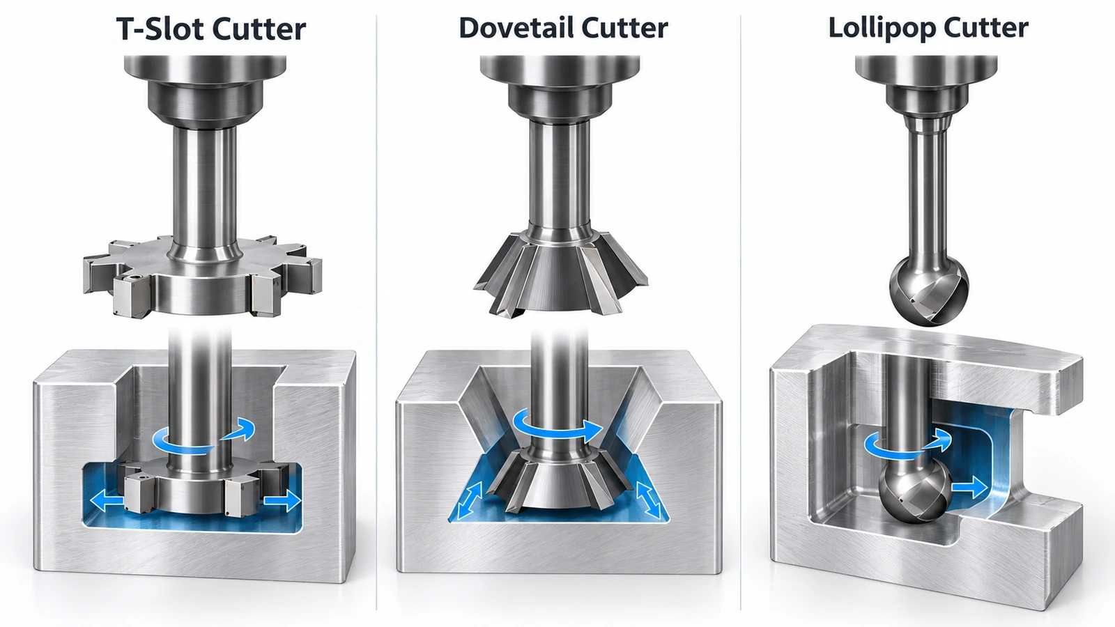
T-Slot Cutters
A T-slot cutter consists of a relatively large cutting head supported by a narrower neck.
It can machine a wider cavity beneath a smaller opening, but the entrance and pre-machined slot must provide sufficient clearance.
Tool diameter, cutting width, neck diameter, and required lateral reach must be checked against the actual cutter drawing.
Dovetail Cutters
Dovetail cutters produce inclined surfaces using an angled cutting profile.
Common tool angles include 45° and 60°, although other angles are available.
Using an available standard cutter can simplify procurement and reduce the need for custom tooling.
Lollipop Cutters
Lollipop cutters have a rounded or ball-like cutting head with a reduced-diameter neck.
They are useful for certain recessed contours and surfaces beneath overhangs, particularly when the machining strategy requires the cutting edge to reach around an obstruction.
However, their reduced neck diameter can limit stiffness.
A longer unsupported tool length increases the risk of deflection, vibration, and poor surface finish.
A cutter that fits inside the opening is not necessarily suitable for the job. The neck, shank, holder, toolpath, and withdrawal movement must also clear the surrounding geometry.
How Are CNC Undercuts Machined?
The machining process begins by determining whether the feature can be reached from an available setup direction.
The manufacturer then selects a suitable cutter and plans the operations required to remove the material.
3-Axis CNC Milling
Many T-slots and dovetail grooves can be machined on a standard 3-axis CNC milling machine.
A typical T-slot process involves:
- Milling an initial straight slot to provide access.
- Selecting a T-slot cutter with suitable head and neck dimensions.
- Entering the prepared opening without tool interference.
- Milling the recessed channel using controlled cutting passes.
- Withdrawing the cutter through a verified clearance path.
- Inspecting the slot dimensions and accessible edges.
This process is practical when the tool can approach the feature from a fixed machining direction.
4-Axis CNC Machining
A 4-axis CNC machine adds a rotational positioning or machining axis.
This can make it easier to machine undercuts on multiple sides of a component or at different angular positions.
For example, an automation component with side-facing recessed features may benefit from rotary indexing.
However, additional rotational capability does not guarantee that a cutter can reach a hidden internal surface.
5-Axis CNC Machining
Five-axis CNC machining allows the tool or workpiece to be oriented at different angles, often reducing the need for repeated manual setups.
It can improve access to complex recessed surfaces, angled pockets, and features that are difficult to machine from fixed directions.
Nevertheless, five-axis machining cannot eliminate physical tool interference.
A cutting tool still needs sufficient space for its cutting head, neck, shank, and holder.
Fully enclosed or deeply obstructed features may remain impossible to machine using conventional cutting tools.
CNC Turning and Alternative Methods
For cylindrical components, internal grooves and relief features are often better suited to CNC turning with specialized grooving tools.
When conventional milling or turning cannot reach the feature, alternative processes may be considered.
Depending on material and geometry, these may include electrical discharge machining (EDM), manufacturing the component as multiple parts, or redesigning the inaccessible region.
The most appropriate solution depends on the feature requirements, material, quantity, and total manufacturing cost.
CNC Undercut Design Guidelines
A well-designed undercut provides sufficient space for cutting, entry, withdrawal, inspection, and any required finishing operations.
The following guidelines can improve manufacturability.
1. Use Standard Cutter Dimensions
Whenever the design allows, select undercut dimensions that match readily available cutters.
For example, a dovetail based on an available 45° or 60° cutter may be easier to manufacture than a feature requiring a special angle.
Similarly, choosing a conventional T-slot profile may avoid custom cutter development.
The objective is not to use a particular size for every design, but to verify that suitable tooling exists before the feature dimensions are finalized.
2. Provide Adequate Tool Entry and Clearance
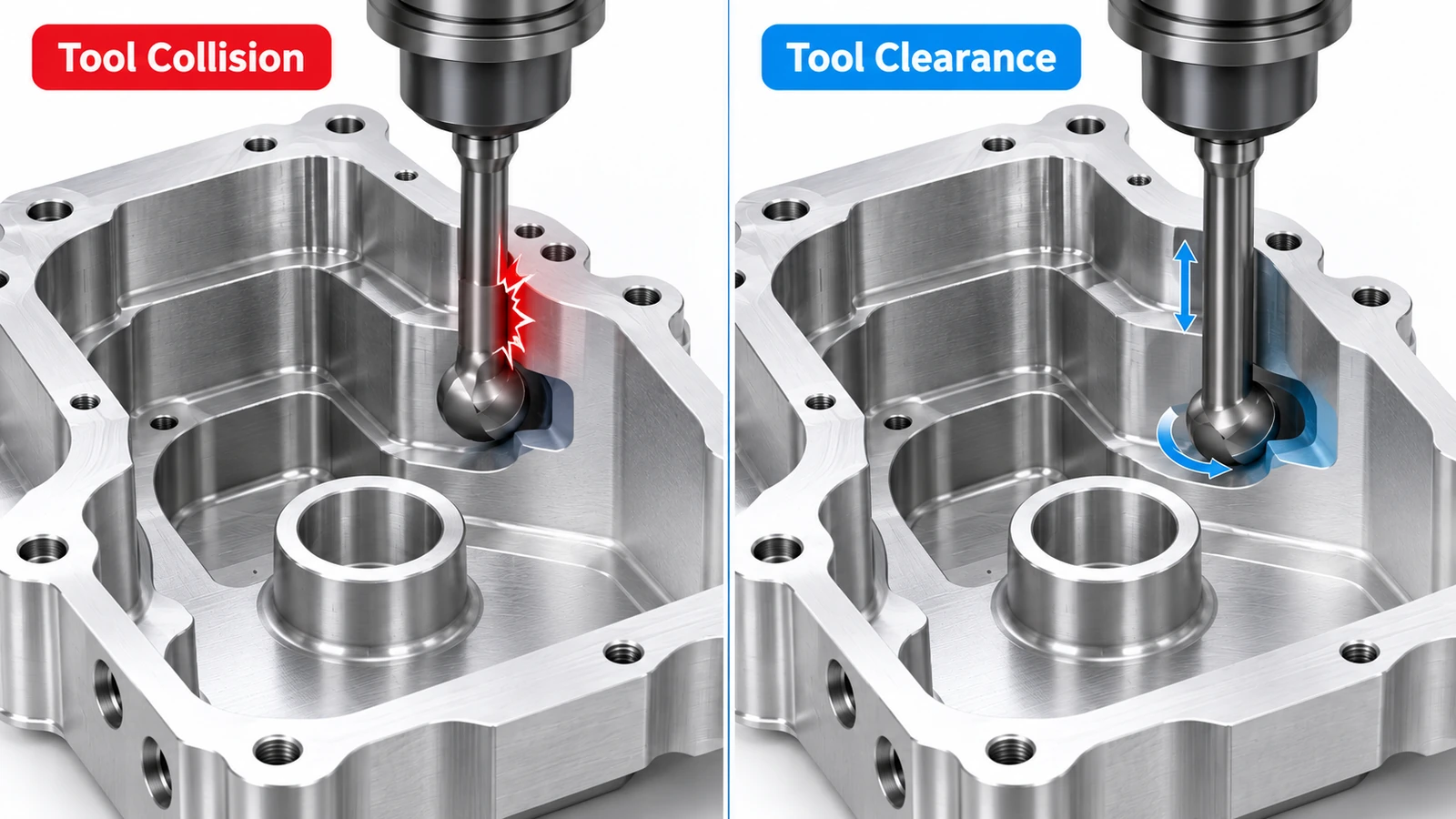
Undercuts frequently become difficult to machine because the cutting head can reach the feature but the cutter neck or holder cannot.
Engineers should check:
- Entrance width and pre-machined access slot.
- Cutter head diameter and cutting width.
- Neck diameter and usable reach.
- Clearance between opposing walls.
- Entry, cutting, and withdrawal paths.
For internal-wall undercuts, some general CNC design guides suggest providing clearance of approximately four times the undercut depth.
This is a preliminary DFM guideline, not a universal minimum. Actual feasibility depends on the selected tool geometry and machining setup.
A tool-envelope check against the CAD model is more reliable than relying on a single clearance ratio.
3. Avoid Unnecessarily Deep Undercuts
Deep undercuts may require cutters with long necks or extended reach.
Longer unsupported tool lengths generally reduce rigidity and can increase cutting deflection.
Where functional requirements allow, a shallower groove or a more accessible geometry can simplify machining.
If the depth cannot be reduced, the manufacturer may need lighter cutting passes, specialized tooling, or a different machining strategy.
4. Specify Tolerances Based on Function
Not every surface inside an undercut requires a tight dimensional tolerance.
For example, the mating faces of a precision dovetail slide may need controlled geometry and surface finish.
A nonfunctional relief surface may not require the same precision.
Specify tight tolerances and inspection requirements for surfaces that influence assembly, alignment, sliding motion, or retention.
Unnecessary precision on inaccessible surfaces can increase manufacturing and inspection effort.
5. Consider Burr Removal and Inspection Access
Hidden grooves may be difficult to deburr after machining.
Burrs can interfere with mating components or become trapped inside an assembly.
Similarly, a cutting tool may successfully machine an internal feature that is difficult to measure using conventional inspection equipment.
Where practical, provide access for edge finishing and measurement, and identify critical dimensions on the engineering drawing.
Common Undercut Machining Problems
Undercut machining can introduce challenges that are less common in open-slot milling.
| Problem | Likely Cause | Recommended Action |
|---|---|---|
| Tool collision | Insufficient neck or holder clearance | Review the complete tool envelope |
| Tool deflection | Long reach or reduced neck stiffness | Shorten overhang or reduce cutting loads |
| Chatter marks | Low rigidity or unstable cutting conditions | Optimize tooling and cutting parameters |
| Poor chip evacuation | Chips trapped inside a recessed groove | Improve coolant direction and chip removal |
| Burrs on hidden edges | Limited deburring access | Plan suitable edge-finishing operations |
| Dimensional variation | Tool wear, runout, or deflection | Control tooling and verify critical dimensions |
Why Is Tool Deflection Important?
Undercut tools often have a cutting head wider than the supporting neck.
This geometry provides access beneath overhanging surfaces, but it may also make the tool less rigid than a conventional end mill of similar cutting diameter.
Excessive deflection can affect groove width, surface quality, and profile accuracy.
Appropriate tooling, stable fixturing, and controlled cutting loads are therefore essential.
Why Are Hidden Burrs Difficult to Remove?
Burrs may form along the inner edges of a T-slot or recessed cavity.
These locations can be difficult to reach with standard deburring tools.
In addition to selecting appropriate cutting conditions, manufacturers may need specialized brushes, controlled manual deburring, or another process suited to the geometry.
For functional grooves, edge requirements should be reviewed before machining begins.
How to Reduce CNC Undercut Machining Costs
Undercut machining cost is influenced by the cutter, toolpath, setup requirements, cutting time, and inspection difficulty.
A design change that improves tool access may reduce several of these cost drivers simultaneously.
DFM Example: Internal Undercut in an Aluminum Housing
Consider a CNC-machined aluminum housing used in industrial automation equipment.
The original CAD design contains a recessed channel beneath an internal wall.
The channel provides clearance for a mating component, but part of the recess lies deep inside the housing.
Original Design
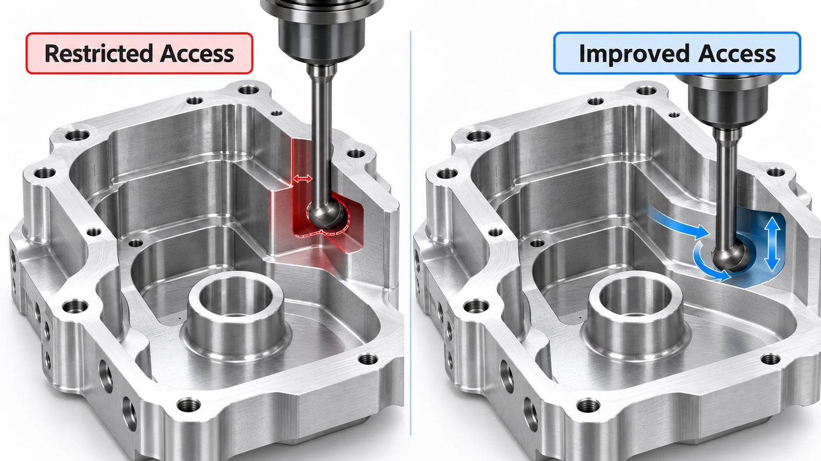
The original structure has several manufacturing challenges:
- The recessed channel is difficult to access.
- A standard end mill cannot reach the hidden surface.
- A long-neck undercut cutter may be required.
- The cutter shank may interfere with the opposite cavity wall.
- Inspection and burr removal are difficult.
Although the feature may be machinable with a suitable specialized setup, it creates additional production risk.
Optimized Design
After reviewing the function of the channel, the designer considers two options.
Option A: Open the Recess
If the overhanging material is not functionally necessary, replace the hidden channel with a more accessible open groove.
This may allow the feature to be machined using a conventional end mill.
Option B: Retain the Undercut but Improve Access
If the overhang is required for retention or assembly, retain the functional undercut while increasing the entrance clearance or selecting a standard cutter-compatible profile.
This preserves the required function while improving tool access.
Original vs Optimized Design
| Design Factor | Original Design | Optimized Design |
|---|---|---|
| Groove accessibility | Restricted | Improved |
| Tool selection | Potentially specialized long-neck cutter | Standard cutter where feasible |
| Collision risk | Higher | Reduced through access review |
| Machining strategy | May require extra operations | Potentially simpler toolpath |
| Deburring | Difficult internal edges | Improved access |
| Inspection | Restricted measurement access | Easier verification |
| Manufacturing cost | Additional tooling and process risks | Potentially lower |
The actual savings depend on the final geometry, available tools, machining material, and production quantity.
No specific cost reduction should be assumed without evaluating the CAD model and manufacturing process.
The best way to reduce undercut machining cost is often to improve the geometry before production, rather than simply choosing a more advanced CNC machine.
Conclusion
CNC undercuts allow designers to create interlocking grooves, internal recesses, and complex mechanical features that cannot always be produced using standard end mills.
Common solutions include T-slot cutters, dovetail cutters, lollipop cutters, internal grooving tools, and multi-axis machining.
However, successful undercut machining depends on more than machine axis count. Cutter geometry, tool access, reach, clearance, and inspection requirements all influence manufacturability.
By using standard cutter-compatible dimensions, avoiding unnecessary depth, and improving access to hidden surfaces, engineers can often simplify manufacturing without sacrificing functionality.
Need CNC-machined parts with complex undercuts or internal features?
YUANYI provides custom CNC milling, multi-axis machining, and DFM support for precision metal and engineering plastic components. Share your CAD files or engineering drawings for a manufacturability review and quotation.
Frequently Asked Questions
Yes. Many T-slots, dovetail grooves, and accessible recessed features can be machined on 3-axis CNC equipment using suitable specialized cutters. The essential requirement is a collision-free toolpath.
No. Many common undercut profiles can be produced using commercially available T-slot, dovetail, or lollipop cutters. Custom tools may be necessary when the profile or access requirements cannot be met using standard tooling.
No. Five-axis machining improves tool orientation and access, but the cutting head, neck, shank, and holder must still physically clear the workpiece.
Depending on the feature, inspection may involve suitable calipers, depth gauges, bore or groove gauges, optical measurement, coordinate measuring machines, or custom functional gauges. The method should match the feature geometry and specified tolerance.
They can be. Stainless steel typically produces higher cutting forces and may create greater tool wear or heat-management challenges than many aluminum alloys. Because undercut cutters may have reduced neck rigidity, the material and cutting conditions can significantly affect machining stability.



