

Knurling is a machining process that creates a repeating pattern of straight, diagonal, or diamond-shaped ridges on a cylindrical surface. It is commonly used to improve grip, enhance appearance, or create mechanical retention features on turned parts.
In CNC machining, knurling is usually performed on a lathe using either form knurling, which displaces material under pressure, or cut knurling, which removes material to produce the pattern.
The choice of pattern, pitch, and method affects surface quality, machining forces, and final part diameter. This guide explains CNC knurling types, machining methods, diameter control, and practical design guidelines for reliable production.
What Is Knurling in CNC Machining?
Knurling produces a regular textured pattern on the outside diameter of a cylindrical workpiece.
Unlike conventional turning, which generally creates a smooth cylindrical surface, knurling produces raised ridges or grooves with a repeating profile.
The process is commonly used on:
- Adjustment knobs and control dials.
- Machine tool handles.
- Thumb screws and thumb nuts.
- Precision instrument components.
- Metal inserts intended for mechanical retention.
- Custom shafts and cylindrical fittings.
For example, a smooth aluminum adjustment knob may be difficult to grip when an operator needs to rotate it manually. Adding a diamond knurl can improve the surface’s grip without requiring a separate rubber covering.
Knurling can also provide a functional interference surface for some press-fit or overmolded components.
However, the appropriate pattern depends on the application. A texture intended for hand gripping may not be suitable for a precision press-fit connection.
Most CNC knurling operations are performed on a rotating workpiece, with a knurling tool engaging the cylindrical surface.
Types of Knurling Patterns
The three commonly discussed knurling patterns are straight, diagonal, and diamond.
Each pattern creates a different surface geometry and may serve a different mechanical purpose.
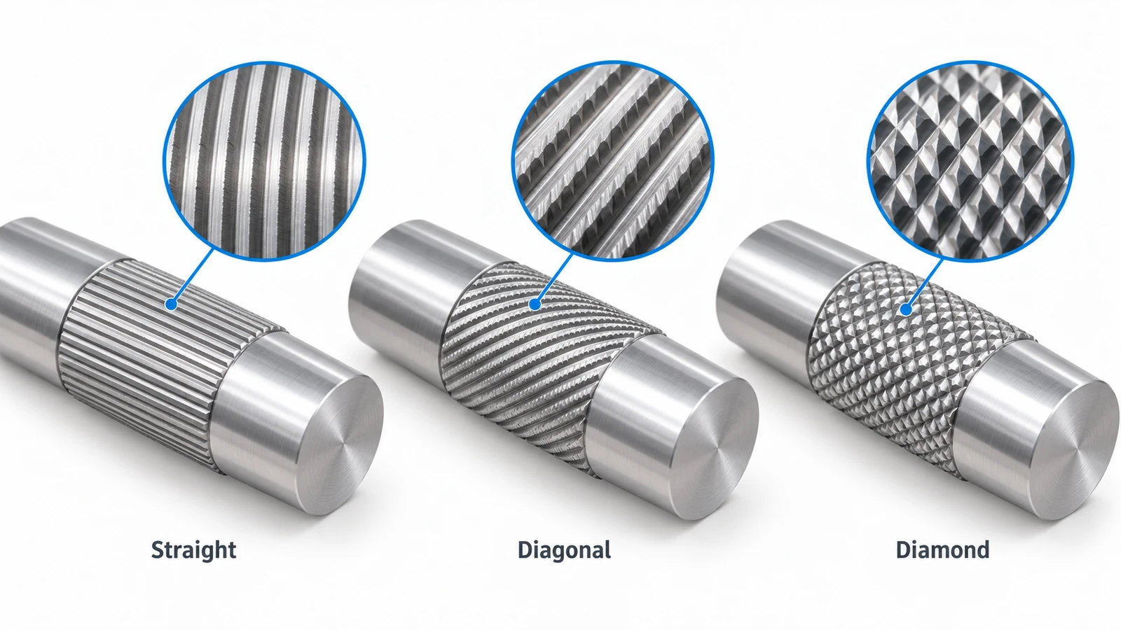
| Knurling Type | Pattern Geometry | Typical Application | Main Consideration |
|---|---|---|---|
| Straight Knurling | Parallel ridges along the workpiece axis | Press-fit features, anti-rotation surfaces | Directional mechanical engagement |
| Diagonal Knurling | Ridges following an inclined or helical direction | Specialized grip and decorative surfaces | Pattern direction and mating requirements |
| Diamond Knurling | Intersecting diagonal ridges forming diamonds | Knobs, handles, thumb screws | Grip, pitch, and surface consistency |
Straight Knurling
Straight knurling creates parallel grooves and ridges running along the axis of a cylindrical component.
This pattern may be used where axial ridges help resist rotation between mating parts.
For example, a straight-knurled metal insert can be designed to engage a surrounding material and resist turning.
However, the retention performance depends on more than the knurl pattern. Insert diameter, surrounding material, engagement length, and assembly method also affect performance.
Straight knurling may also be selected for its appearance or a particular directional surface texture.
Diagonal Knurling
Diagonal knurling produces ridges inclined relative to the workpiece axis.
Depending on the selected tool and geometry, the pattern may follow a right-hand or left-hand direction.
It can be useful where a particular surface appearance or directional interaction is required.
Compared with standard straight or diamond patterns, specialized diagonal configurations may require additional tooling or drawing specifications.
Diamond Knurling
Diamond knurling creates a crossed pattern of diagonal ridges.
The intersections form a series of diamond-shaped peaks and recesses.
This is a common choice for manually operated knobs, handles, and thumb screws because the multidirectional texture provides useful gripping surfaces.
Diamond knurling is also visually distinctive, making it suitable for exposed precision components.
However, a deeper or sharper pattern is not automatically better. Excessively aggressive knurling may be uncomfortable to handle or difficult to clean.
Pattern selection should be based on the required function rather than appearance alone.
Form Knurling vs Cut Knurling
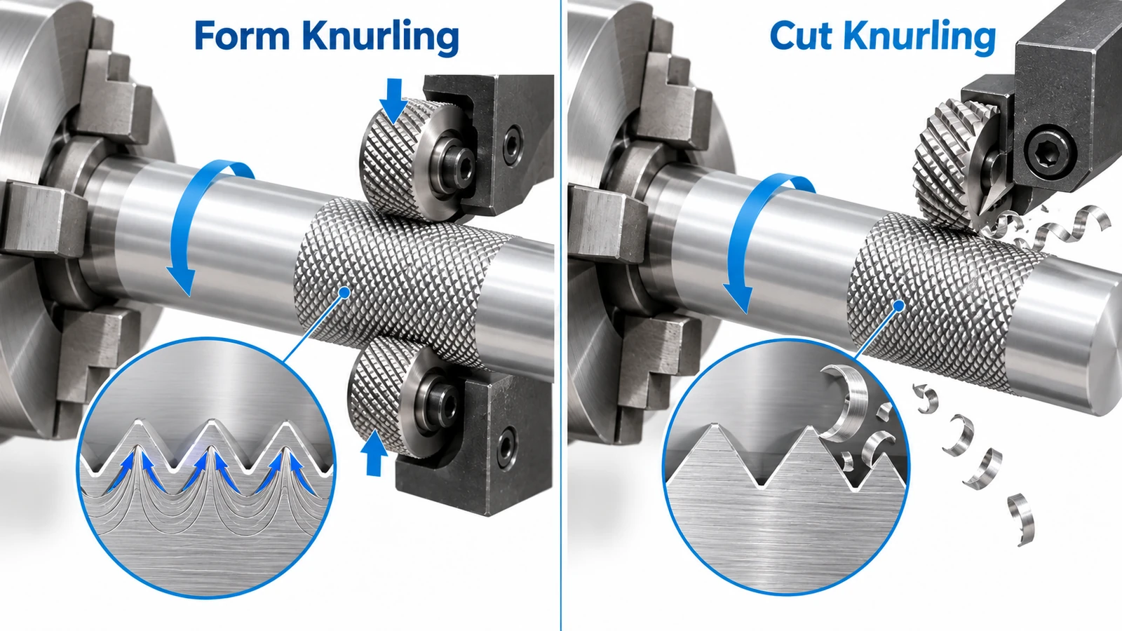
The two main CNC knurling methods are form knurling and cut knurling.
Although both produce textured surfaces, their material-removal mechanisms and machining requirements are different.
| Feature | Form Knurling | Cut Knurling |
|---|---|---|
| Process | Plastic deformation | Material removal |
| Material behavior | Surface metal is displaced | Material is cut into chips |
| Cutting chips | Normally none from the forming operation | Produced during cutting |
| Machining loads | Often higher forming forces | Generally lower radial forces |
| Diameter effect | Raised material can increase peak diameter | Surface geometry is created by cutting |
| Thin-wall parts | Greater deformation concerns | Often preferable for load-sensitive workpieces |
| Tooling | Forming wheels | Dedicated cutting knurl tools |
How Form Knurling Works
Form knurling uses hardened patterned wheels pressed against the rotating workpiece.
As the tool applies pressure, the workpiece surface plastically deforms.
Material flows into the wheel’s profile, producing raised ridges and recessed areas.
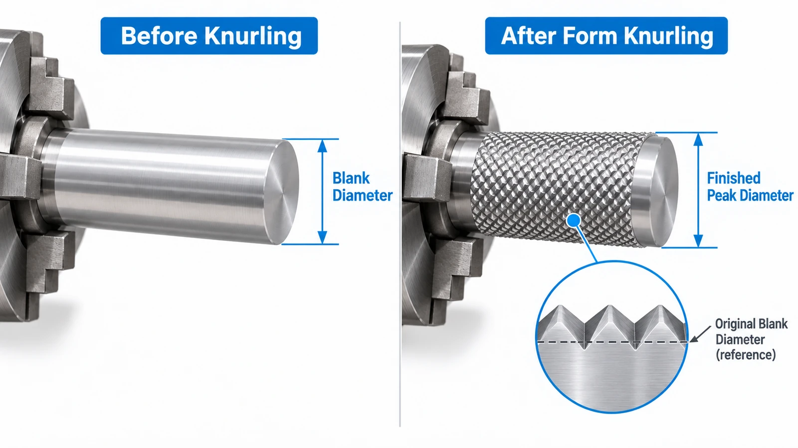
Because material is displaced rather than removed, the peak diameter of the finished knurl can become larger than the original blank diameter.
This is particularly important when the final outside diameter affects component assembly.
Form knurling is frequently used on materials capable of plastic deformation, including many aluminum alloys, brass alloys, and steels.
However, the required forming force can be substantial.
Thin-walled tubes, slender shafts, and poorly supported parts may deform or deflect under excessive pressure.
How Cut Knurling Works
Cut knurling uses cutting edges to remove material and generate the intended surface profile.
Unlike forming, the process creates chips.
Cut knurling can reduce the radial loading associated with conventional form knurling, making it useful for certain thin-walled, slender, or harder-to-form components.
It may also offer greater control over the generated profile when the tool, setup, and cutting conditions are appropriate.
However, cut knurling requires suitable equipment and tooling. It is not automatically faster, cheaper, or more accurate in every application.
The most suitable method depends on material, part rigidity, required pattern, production quantity, and dimensional requirements.
How Does CNC Knurling Work?
CNC knurling is typically performed after the workpiece has been turned to an appropriate blank diameter.
The exact sequence depends on whether the part is form-knurled or cut-knurled.
Step 1: Prepare the Workpiece
The workpiece is turned to the specified pre-knurl diameter.
This dimension must account for the selected knurling process and the required final surface geometry.
The blank diameter should not be chosen solely from the nominal finished outside diameter.
Step 2: Select and Align the Knurling Tool
The operator or programmer selects a knurling tool that matches the required pattern and pitch.
Correct tool alignment is essential.
A misaligned tool may produce uneven ridges, excessive forces, or an irregular surface.
For forming operations, the tool configuration should also account for how forces are supported by the machine and workpiece.
Step 3: Establish the Pattern
The knurling wheels engage the rotating workpiece under controlled conditions.
The tool must establish a consistent repeating pattern rather than producing overlapping or divided tracks.
Workpiece diameter, tool pitch, feed, and initial engagement all influence the result.
Step 4: Complete the Knurled Length
Once the pattern is established, the tool progresses along the required surface length, where applicable.
Cutting speed, feed, tool pressure, lubrication, and tool condition should follow the selected tooling manufacturer’s recommendations.
The process must also avoid unintended contact with shoulders, adjacent diameters, or other finished features.
Step 5: Inspect the Finished Surface
After machining, the operator checks whether the finished knurl meets the drawing requirements.
Inspection may include pattern type, pitch, knurled length, peak diameter, visible defects, and functional fit.
For critical applications, a representative mating-part or functional gauge test may also be appropriate.
Knurling Pitch and Diameter Control
Knurling pitch and outside diameter are among the most important design variables.
Incorrectly specified dimensions can produce double tracking, inconsistent patterns, or parts that no longer fit their intended assemblies.
What Is Knurling Pitch?
Knurling pitch describes the spacing of the repeating tooth pattern.
However, the term pitch is not always used in exactly the same way across different tooling systems.
Metric linear pitch, diametral pitch, and module-based specifications are distinct systems. They should not be interchanged without confirming their definitions.
ISO 13444:2012 provides standardized guidance for dimensioning and indicating common knurling patterns.
When selecting a knurl, engineers should verify that the pitch designation used on the drawing matches the tool manufacturer’s system.
Why Does Knurling Change the Diameter?
In form knurling, the tool presses material into a new profile.
Material displaced from the grooves forms the raised peaks.
Consequently, the finished peak diameter may exceed the original turned blank diameter.
The amount of change depends on several factors:
- Knurling pitch and tooth geometry.
- Workpiece material and its deformation behavior.
- Forming depth and tool pressure.
- Knurling wheel condition.
- Actual process setup.
Therefore, a universal allowance such as “turn every blank 0.1 mm undersize” is not reliable.
Cut knurling behaves differently because material is removed. Even so, the actual finished diameter must be established from the intended cutting profile and process requirements.
How to Prevent Double Tracking
A properly formed pattern should repeat consistently around the circumference.
When the effective pitch and workpiece circumference do not produce stable tracking, or the tool fails to establish the pattern correctly, the knurl may develop overlapping or doubled tracks.
For a simple straight pattern where linear tooth spacing is defined around the circumference, a preliminary relationship is:
N ≈ πD / P
Where:
- N = approximate number of pattern repeats around the circumference
- D = relevant workpiece diameter
- P = corresponding circumferential pitch
This relationship illustrates why diameter and pitch interact.
It is not a universal setup formula for diamond knurling or every cut-knurling tool system. Helix geometry, the particular pitch definition, and the tool manufacturer’s instructions must also be considered.
For production, use the selected tool manufacturer’s diameter and pitch guidance and confirm the result through trial machining where necessary.
CNC Knurling Design Guidelines
A successful knurling design should define both the surface pattern and its functional requirements.
A drawing that simply states “KNURL” may leave too much room for interpretation.
1. Specify the Required Pattern
Identify whether the component needs straight, diamond, or another pattern.
If the surface must resist rotation, improve grip, or serve as a decorative feature, communicate that function.
Pattern selection should not rely on the manufacturer’s assumptions.
2. Define Pitch and the Applicable Standard
Specify the required pitch using a clearly identified system.
Where applicable, reference ISO 13444 or another agreed drawing or tooling specification.
Avoid mixing metric linear pitch and diametral pitch terminology without clarification.
3. Clarify the Finished Diameter
State whether an outside diameter applies to the pre-knurled blank or to the finished knurl peaks.
For mating components, this distinction is essential.
A drawing may require a controlled maximum finished diameter to prevent assembly interference.
Conversely, a retained insert may require a defined knurled envelope to achieve the intended mechanical engagement.
The manufacturer should confirm the necessary pre-machining diameter based on the process.
4. Define Knurled Length and Edge Conditions
Specify the axial length and location of the knurled region.
Consider the distance from adjacent shoulders, grooves, threads, and precision diameters.
Tool entry and exit may produce incomplete patterns near the ends, depending on the selected process.
If the complete length must have a full-height pattern, this requirement should be discussed before production.
5. Match the Process to the Material
Material properties influence how a knurled surface is formed.
Aluminum and brass often permit relatively straightforward forming, while some stainless steels require greater attention to forces, work hardening, and tool wear.
Thin-walled parts need particular care because excessive forming pressure may distort the cylinder.
DFM Example: Ø20 mm Aluminum Adjustment Knob
Consider a custom adjustment knob machined from 6061 aluminum.
The required features are:
| Design Item | Example Requirement |
|---|---|
| Component | Manual adjustment knob |
| Material | Aluminum 6061 |
| Finished knurled outside diameter | Ø20.00 mm nominal |
| Knurled length | 12 mm |
| Pattern | Diamond |
| Function | Hand gripping |
| Process | Form or cut, subject to manufacturing review |
These values describe an illustrative design, not a validated manufacturing recipe.
The designer should additionally specify the pattern pitch, finished diameter limits, edge requirements, and any applicable drawing standard.
If form knurling is selected, the manufacturer must account for material displacement when determining the pre-knurled blank diameter.
If cut knurling is selected, the tool geometry and cutting strategy must provide the required finished profile.
For either method, a first-article inspection can help confirm pattern quality and finished dimensions before repeat production.
The key is to control the finished functional geometry, rather than assume that the turned blank diameter will remain unchanged after knurling.
Common Knurling Defects and Solutions
Poor knurling quality can affect both appearance and performance.
The following problems are commonly associated with incorrect tool selection, setup, or process conditions.
| Defect | Possible Cause | Recommended Action |
|---|---|---|
| Double Tracking | Incorrect pitch/diameter relationship or unstable initial engagement | Review tool pitch, blank diameter, and setup |
| Incomplete Pattern | Insufficient engagement or inconsistent forming/cutting | Verify tool alignment and process settings |
| Surface Tearing | Excessive pressure, unsuitable conditions, or material behavior | Adjust process and check lubrication |
| Chatter Marks | Weak support or unstable cutting conditions | Improve rigidity and tool setup |
| Uneven Knurl Depth | Misalignment, deflection, or worn wheels | Check tool position and condition |
| Finished Diameter Out of Tolerance | Incorrect pre-knurl size or uncontrolled material flow | Validate blank diameter and inspect finished peaks |
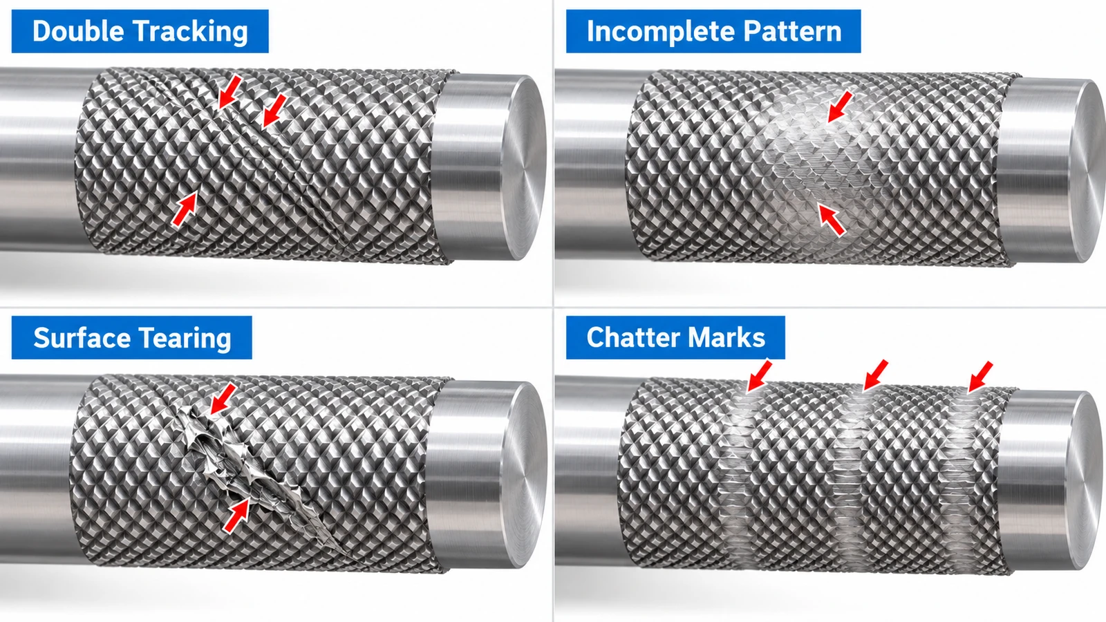
Double Tracking
Double tracking produces an irregular pattern when the tool creates multiple competing tracks rather than following a consistent profile.
It can occur when the selected pitch, blank diameter, and initial engagement are not compatible with the tooling and setup.
Possible corrective actions include reviewing the workpiece diameter, checking wheel condition, and following the tool manufacturer’s recommended engagement procedure.
Workpiece Deformation
Form knurling can generate significant forces.
A slender shaft may deflect, while a thin-walled tube may become distorted.
Appropriate workholding, support, and tool selection can reduce these risks.
For some sensitive components, cut knurling may be a more suitable option.
Poor Pattern Quality
Torn peaks, incomplete ridges, or inconsistent texture may result from poor alignment, tool wear, unsuitable material conditions, or unstable process parameters.
Visual inspection is helpful, but important functional features should also be checked against measurable acceptance criteria.
Conclusion
CNC knurling creates functional and decorative surface patterns on turned components.
Straight, diagonal, and diamond patterns serve different purposes, while form and cut knurling use different manufacturing mechanisms.
For engineering design, the most important considerations are pattern selection, pitch specification, finished diameter control, material behavior, and inspection requirements.
Correctly defining these features on the drawing helps manufacturers produce consistent knurled parts while reducing avoidable defects and rework.
Need custom CNC-turned components with knurled surfaces?
YUANYI provides precision CNC turning and manufacturability support for custom metal and engineering plastic components. Send us your CAD files or engineering drawings to discuss your project requirements and request a quotation.
Frequently Asked Questions
It depends on the method. Form knurling creates the pattern through plastic deformation, while cut knurling removes material. Both are used to produce knurled surfaces.
Yes. Many stainless steels can be knurled using appropriate tooling and process conditions. However, material strength, work hardening, and tool wear must be considered.
Not necessarily. Knurling changes the surface geometry but does not automatically increase the structural strength of a shaft. The grooves and local deformation may also influence stress concentration or fatigue performance.
Yes, depending on the tube dimensions, material, tooling, and support. Form knurling may cause deformation because of its forming forces. Cut knurling or a supported process may be preferable in some cases.
Aluminum knurled parts can be anodized, but the coating may influence appearance, surface texture, and finished dimensional requirements. Critical fits should account for the applicable coating process.



