

Tool deflection occurs when a cutting tool bends slightly under machining forces, causing the cutting edge to move away from its programmed position. In CNC milling, excessive deflection can cause dimensional errors, tapered walls, chatter, poor surface finish, and accelerated tool wear.
The problem is most common when machining deep pockets, tall walls, narrow slots, or features that require a small-diameter cutter with long tool stickout.
The main factors are tool overhang, cutter diameter, cutting force, tool material, and toolholder rigidity.
What Is Tool Deflection in CNC Machining?
During milling, cutting forces act on the end mill as it removes material. Because the tool is elastic rather than perfectly rigid, the unsupported portion can bend slightly.
For example, if a cutter is programmed to finish a wall at:
X = 50.000 mm
but cutting force pushes the tool away by 0.02 mm, the actual surface may be machined near:
X = 50.020 mm
The CNC machine may still be positioning correctly. The error comes from the tool bending under load.
Tool deflection is especially important in deep-pocket machining because longer tools are less rigid and more sensitive to lateral cutting forces.
What Causes Tool Deflection?
Several factors influence cutter deflection.
| Factor | Effect |
|---|---|
| Tool stickout | Longer stickout greatly increases deflection |
| Cutter diameter | Larger diameter increases stiffness |
| Cutting force | Higher force increases deflection |
| Radial engagement | Greater engagement usually increases lateral force |
| Workpiece material | Harder materials generally require higher cutting force |
| Toolholder rigidity | Flexible setups increase total displacement |
| Tool wear | Worn edges can increase cutting load |
Tool Stickout
Tool stickout is the unsupported distance between the holder and the cutting area.
The longer this distance becomes, the more easily the tool bends.
This is why deep pockets often create greater deflection problems than shallow features, even when using the same cutter diameter.
Cutter Diameter
Cutter diameter also has a major effect on stiffness.
A larger end mill generally resists bending much better than a smaller one.
This is one reason very small internal corner radii can make CNC machining more difficult: they force the use of smaller tools.
Why Tool Length and Diameter Matter So Much
A simplified tool-deflection model treats the cutter as a cantilever beam:
δ = FL3 / 3EI
where:
- δ = tool deflection
- F = cutting force
- L = unsupported tool length
- E = elastic modulus
- I = area moment of inertia
For a round tool:
I = πD4 / 64
This gives a useful simplified relationship:
Tool Deflection ∝ FL3 / ED4
The equation is not a complete machining simulation because real end mills contain flutes, changing engagement, holder compliance, and dynamic cutting forces.
However, it clearly shows two important trends.
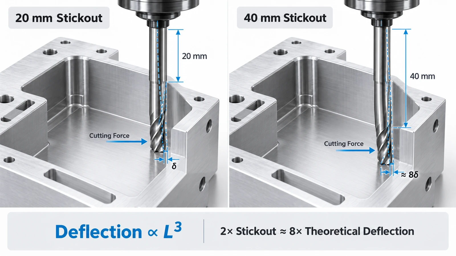
Longer Stickout Quickly Increases Deflection
Deflection increases approximately with the cube of tool length.
If tool stickout increases from:
20 mm → 40 mm
the unsupported length doubles.
In the simplified model:
403 / 203 = 8
So doubling stickout can result in approximately eight times the theoretical deflection.
This is why unnecessary tool overhang should be avoided.
Larger Diameter Greatly Improves Stiffness
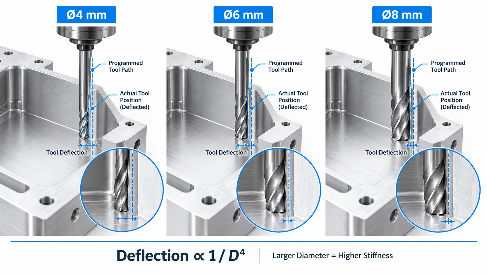
Tool stiffness is strongly influenced by diameter because the area moment of inertia depends on D4.
Therefore, even a moderate increase in cutter diameter can greatly reduce deflection.
When possible, designers should allow larger internal corner radii so larger and more rigid tools can be used.
How Tool Deflection Affects CNC Parts
Excessive deflection can create several machining problems.
Dimensional Error
During side milling, the cutter may bend away from the surface.
This can result in:
- Undersized pockets.
- Oversized external features.
- Incorrect slot widths.
- Location errors.
Wall Taper
With long-reach tools, deflection may vary with cutting depth.
A deep pocket wall may therefore become slightly tapered instead of perfectly vertical.
Poor Surface Finish and Chatter
A flexible cutter can repeatedly bend and recover during machining.
This may create:
- Wavy surfaces.
- Uneven tool marks.
- Chatter patterns.
- Reduced finishing consistency.
Tool deflection and chatter are not the same phenomenon, but a flexible cutting system is generally more prone to vibration.
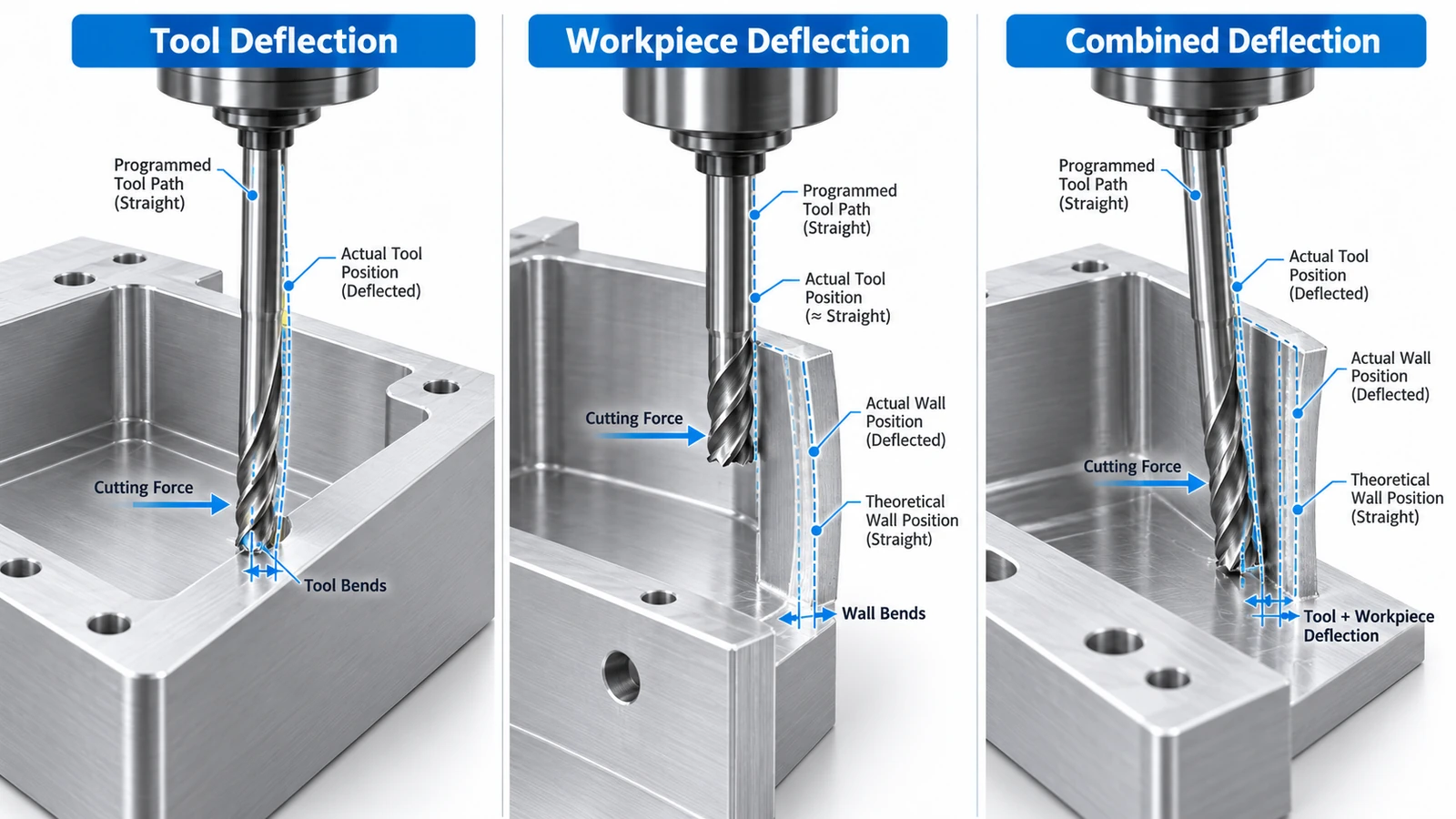
Tool Deflection vs Workpiece Deflection
Not every machining error is caused by the cutter.
The workpiece itself can also bend.
Tool Deflection
The cutter bends while the part remains relatively rigid.
This is common with:
- Long-reach tools.
- Small-diameter end mills.
- Deep pockets.
- High radial cutting forces.
Workpiece Deflection
The workpiece bends away from the cutter.
This is common when machining:
- Thin walls.
- Tall ribs.
- Thin plates.
- Slender features.
For example, when finishing a thin aluminum wall, the wall may move away during cutting and spring back afterward.
Both Can Happen Together
A deep thin-wall pocket may involve both:
tool deflection + workpiece deflection
In this situation, simply adjusting cutter compensation may not solve the problem because the amount of movement changes with cutting force and remaining material thickness.
How to Reduce Tool Deflection
The most effective solutions focus on reducing cutting force and increasing system rigidity.
1. Reduce Tool Stickout
Use only the length required to safely reach the feature.
Shortening unnecessary overhang is often the easiest and most effective improvement.
2. Use the Largest Practical Cutter
When the geometry allows it, use a larger-diameter end mill.
Designers can help by avoiding unnecessarily small internal corner radii.
3. Reduce Radial Engagement
Smaller radial depth of cut generally reduces lateral cutting force.
This is particularly useful when using long-reach tools.
4. Leave Finishing Stock
Avoid trying to achieve final dimensions during aggressive roughing.
Leave a controlled amount of stock, then remove it using a light finishing pass.
This gives the cutter a more consistent and lower cutting load.
5. Use Semi-Finishing and Final Finishing Passes
For demanding deep walls, a semi-finishing pass followed by a light final pass can improve dimensional consistency.
6. Improve Toolholding
Use rigid holders, minimize extensions, control runout, and keep toolholder and spindle contact surfaces clean.
Toolholder flexibility and runout can increase effective tool displacement even when the cutter itself is relatively stiff.
7. Maintain Stable Tool Engagement
Avoid sudden changes in cutter engagement, especially in internal corners.
Smooth toolpaths and controlled radial engagement help keep cutting forces more predictable.
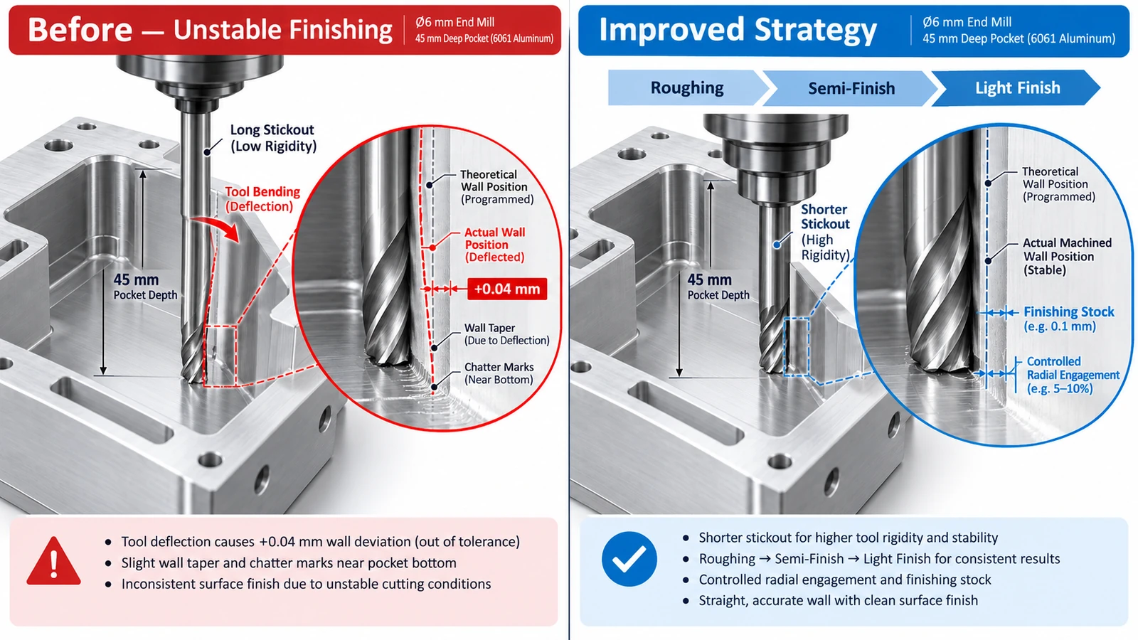
CNC Tool Deflection Example: Deep Aluminum Pocket
Consider a 6061 aluminum housing with:
- 45 mm pocket depth
- Ø6 mm end mill
- Long tool stickout
- Tight wall tolerance
After finishing, inspection shows that the lower section of the wall is approximately:
+0.04 mm oversized
and the surface finish becomes worse near the bottom of the pocket.
The likely cause is the combination of:
small cutter + long stickout + lateral cutting force
Instead of simply changing the tool offset, a better machining strategy would be:
- Use the shortest practical Ø6 mm cutter.
- Reduce radial engagement.
- Leave controlled finishing stock.
- Use a semi-finishing pass.
- Finish with a light final pass.
- Measure the wall at several depths.
This approach reduces cutting force and improves stability rather than compensating for an unstable process.
Conclusion
CNC tool deflection occurs when cutting forces bend the cutter away from its programmed position.
The most important factors are tool stickout, cutter diameter, cutting force, and toolholding rigidity.
In practice, the most effective solutions are usually straightforward:
shorter stickout + larger cutter + controlled engagement + light finishing passes
For deep pockets and precision walls, controlling deflection is often more effective than trying to correct the final error with tool offsets alone.
YUANYI can review CAD files and drawings before machining to identify deep pockets, thin walls, small internal radii, and other features that may be sensitive to tool or workpiece deflection.
Frequently Asked Questions
A longer unsupported tool is generally less rigid, but actual deflection also depends on cutter diameter, cutting force, tool material, and toolholder stiffness.
Small, consistent errors may sometimes be compensated. However, compensation does not solve unstable or changing deflection caused by varying cutting forces.
No. Tool deflection is elastic bending under load, while chatter is vibration in the machining system. However, excessive flexibility can increase the risk of chatter.
Avoid unnecessarily deep narrow pockets, very small internal radii, and tight tolerances on hard-to-reach walls. Allowing larger cutters and better tool access usually improves rigidity.



