

An end mill is a rotary cutting tool used in CNC milling to machine slots, pockets, contours, and flat or curved surfaces. Unlike a conventional drill bit, which primarily cuts along its axis, an end mill can remove material with its peripheral cutting edges and, depending on its design, its end cutting edges.
End mills are widely used to manufacture aluminum brackets, steel components, precision housings, molds, and engineering plastic parts.
The right end mill depends on the workpiece material, cutting operation, tool diameter, flute count, and machining conditions. Choosing suitable geometry improves chip evacuation, surface finish, dimensional accuracy, and tool life.
How Does an End Mill Work?
An end mill removes material as its rotating cutting edges engage the workpiece along a programmed toolpath.
In CNC milling, the machine controls the relative movement between the rotating cutter and the workpiece. Each cutting edge removes a small amount of material, producing chips as the required shape is formed.
Unlike conventional drill bits, end mills are designed to perform a variety of lateral cutting operations, including:
- Slot and groove milling
- Pocket machining
- Side and shoulder milling
- Profile and contour machining
- Three-dimensional surface finishing
Some center-cutting end mills can also cut axially into material. However, this does not mean every center-cutting tool is suitable for direct vertical plunging.
The appropriate entry strategy depends on the cutter geometry, workpiece material, and manufacturer’s recommendations. Ramping or helical entry may be preferable to direct plunging.
What Are the Main Parts of an End Mill?
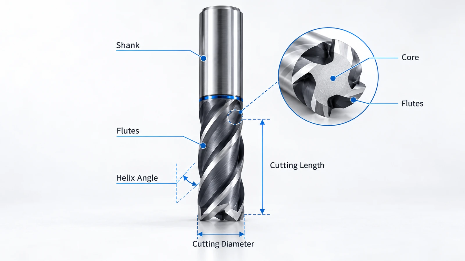
End mill geometry influences cutting performance, chip evacuation, rigidity, and the features that can be machined.
| End Mill Feature | Function | Machining Consideration |
|---|---|---|
| Cutting diameter | Determines the nominal tool width | Controls feature accessibility and affects stiffness |
| Flutes | Provide cutting edges and chip channels | Affect chip evacuation and cutting engagement |
| Helix angle | Defines the spiral cutting-edge orientation | Influences cutting forces and chip flow |
| Shank | Connects the tool to the holder | Requires secure clamping and low runout |
| Cutting length | Defines the usable axial cutting edge | Affects machining depth and tool rigidity |
| Corner geometry | Defines the end cutting profile | Determines achievable part features |
| Core diameter | Forms the central body of the tool | Influences bending strength and stiffness |
Why Does Flute Count Matter?
Flutes provide both cutting edges and space for chip evacuation.
End mills with fewer flutes generally have larger chip channels, which can help when machining materials that generate relatively large chips.
Tools with more flutes provide additional cutting edges and may support higher feed rates under suitable conditions. However, reduced chip space can increase the risk of chip packing.
The best flute count depends on the material, tool geometry, cutting engagement, and chip removal conditions.
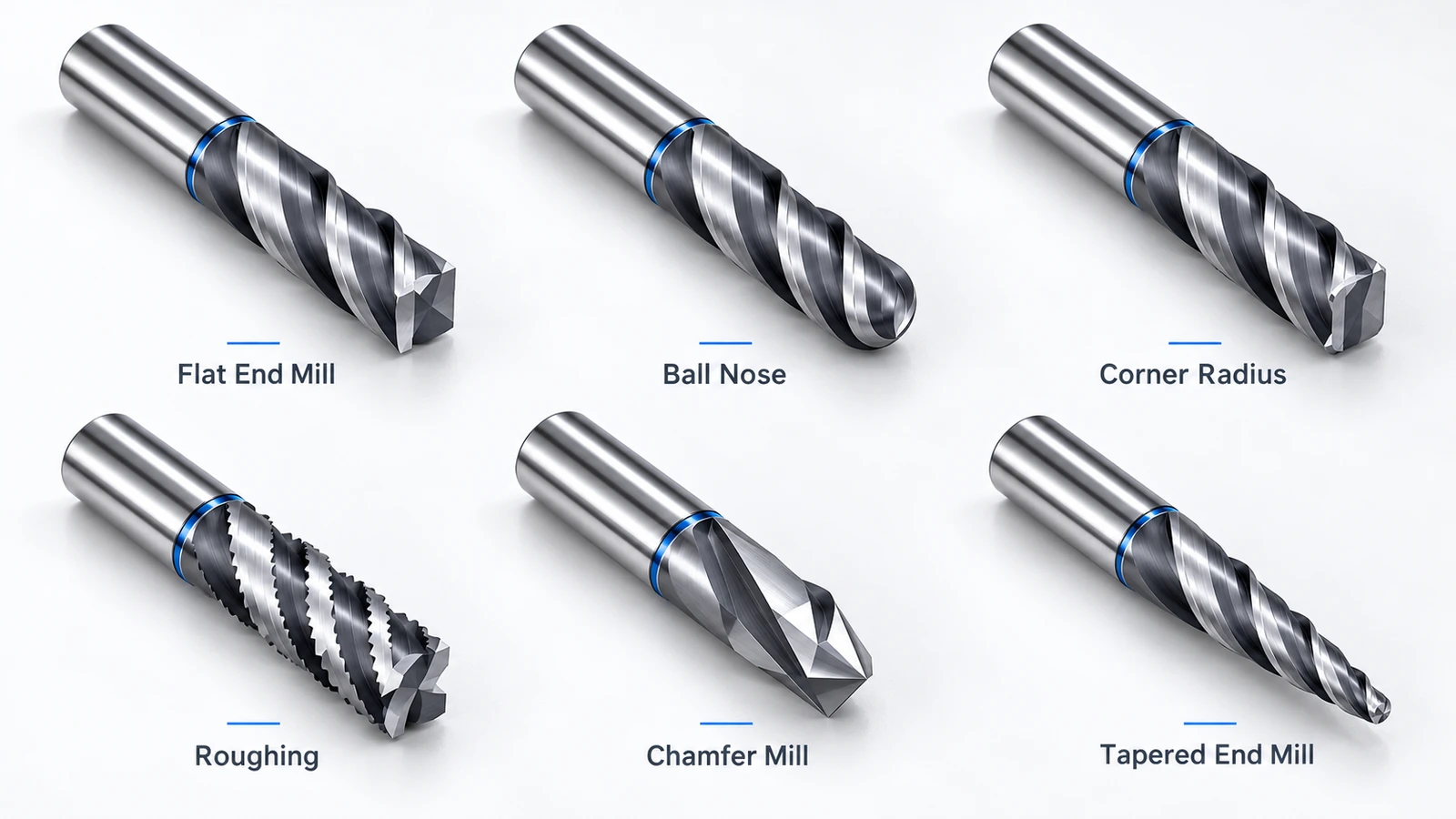
Types of End Mills and Their Uses
Different end mill types are designed for specific cutting operations and workpiece geometries.
1. Flat End Mills
Flat end mills have a generally flat cutting end and peripheral cutting edges.
They are commonly used for slots, flat-bottom pockets, shoulders, and external profiles.
Their versatile geometry makes them suitable for many general-purpose roughing and finishing operations.
2. Ball Nose End Mills
Ball nose end mills have a hemispherical cutting tip designed for machining curved and three-dimensional surfaces.
They are commonly used in mold making, die manufacturing, complex surface finishing, and multi-axis machining.
The resulting surface finish depends on the tool radius, stepover, tool orientation, and cutting conditions.
3. Corner Radius End Mills
Corner radius end mills, also known as bull nose end mills, combine a generally flat end with radiused cutting corners.
The radius can improve cutting-edge strength compared with a sharp corner, making these cutters useful for certain roughing and finishing operations.
They are also suitable for machining shoulders and internal features requiring a specified corner radius.
4. Roughing End Mills
Roughing end mills typically use serrated or interrupted cutting edges to break chips into smaller segments.
They are designed for efficient material removal and can help manage chip formation and cutting loads.
However, their cutting geometry often produces a relatively rough surface, so a separate finishing pass may be necessary.
5. Chamfer Mills
Chamfer mills have angled cutting edges designed to produce chamfers and beveled edges.
They are commonly used for edge preparation, deburring, and machining specified angled features.
6. Tapered End Mills
Tapered end mills have a cutting diameter that changes along the tool axis.
They are used for tapered walls, mold cavities, angled features, and certain deep machining applications.
Some tapered designs also provide greater stiffness than straight cutters with a comparable minimum cutting diameter.
End Mill Types Comparison
| End Mill Type | Primary Application | Main Characteristic |
|---|---|---|
| Flat End Mill | Slots, pockets, flat surfaces | Flat cutting end |
| Ball Nose End Mill | 3D surfaces and curved contours | Hemispherical tip |
| Corner Radius End Mill | Shoulders and radiused features | Strengthened cutting corners |
| Roughing End Mill | Bulk material removal | Serrated cutting geometry |
| Chamfer Mill | Chamfers and edge preparation | Angled cutting edges |
| Tapered End Mill | Tapered walls and mold cavities | Tapered cutting profile |
For more information about the processes these tools perform, see our Types of Milling Operations guide.
2-Flute vs. 3-Flute vs. 4-Flute End Mills
Flute count affects chip evacuation, tool geometry, and the number of cutting edges engaged during machining.
| Feature | 2-Flute End Mill | 3-Flute End Mill | 4-Flute End Mill |
|---|---|---|---|
| Chip space | Generally larger | Intermediate | Generally smaller |
| Common materials | Aluminum, plastics | Aluminum, general-purpose alloys | Steel, stainless steel |
| Typical applications | Slotting and chip-intensive cuts | Aluminum roughing and finishing | General milling and finishing |
| Cutting edges | 2 | 3 | 4 |
| Main consideration | Chip clearance | Balance of chip space and cutting edges | Chip evacuation at higher engagement |
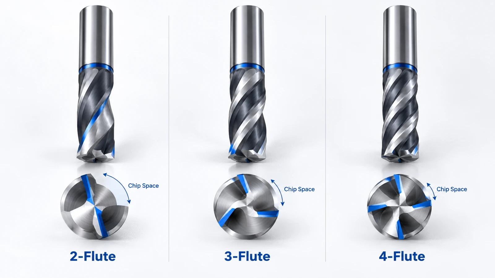
These are common application patterns, not fixed rules. Specialized 4-flute and higher-flute-count end mills can also machine aluminum efficiently under suitable conditions.
When Should You Use a 2-Flute End Mill?
Two-flute end mills are commonly used for aluminum and engineering plastics.
Their relatively large flute spaces help evacuate chips during slotting and other operations with substantial tool engagement.
However, their suitability depends on the cutter design and machining strategy rather than flute count alone.
When Is a 3-Flute End Mill Better?
Three-flute end mills are widely used for aluminum machining.
They can offer a useful balance between cutting-edge count and chip evacuation, particularly when designed specifically for aluminum alloys.
They may perform well in both roughing and finishing operations.
When Should You Choose a 4-Flute End Mill?
Four-flute end mills are commonly used for steel, stainless steel, and general-purpose machining.
Additional cutting edges can support higher table feeds at a given feed per tooth and spindle speed, provided the cutting conditions and machine capabilities allow it.
Four-flute tools may also be suitable for aluminum when their geometry and chip evacuation capabilities match the operation.
Flute count should be selected according to the complete cutting process, not workpiece material alone.
Carbide vs. HSS End Mills: Which Is Better?
Solid carbide and high-speed steel (HSS) are common materials used to manufacture end mills.
| Property | Solid Carbide | HSS |
|---|---|---|
| Hardness | Generally higher | Lower |
| Wear resistance | Generally higher | Lower |
| Cutting speed capability | Often higher | Usually lower |
| Elastic modulus | Higher | Lower |
| Resistance to impact and chipping | More brittle | Generally tougher |
| Purchase price | Usually higher | Usually lower |
| Typical use | Precision CNC production | General-purpose and lower-speed machining |
Solid Carbide End Mills
Solid carbide end mills provide high hardness, wear resistance, and stiffness potential.
They are widely used in modern CNC machining centers, particularly for production applications requiring efficient cutting performance and consistent dimensional results.
However, carbide is relatively brittle and may chip or fracture under unstable machining conditions.
HSS End Mills
HSS end mills generally cost less and are more tolerant of certain impact or interrupted cutting conditions.
They are useful for manual milling machines, less rigid equipment, and lower-speed applications.
Compared with carbide, HSS typically requires lower cutting speeds under similar conditions.
The actual stiffness and stability of either tool also depend on diameter, flute geometry, overhang, toolholding, and cutting forces.
How to Choose the Right End Mill for CNC Machining
Selecting the correct end mill involves matching the cutting tool to the material, geometry, machine capabilities, and required surface quality.
1. Match the End Mill to the Material
Different materials require different cutting geometries and operating conditions.
| Workpiece Material | Common Tool Selection Considerations |
|---|---|
| Aluminum | Sharp cutting edges, effective chip evacuation, suitable anti-adhesion geometry |
| Stainless Steel | Strong cutting edges, appropriate coatings, controlled cutting temperatures |
| Titanium | Heat management, stable engagement, suitable tool geometry |
| Brass | Appropriate edge geometry and stable chip formation |
| Engineering Plastics | Sharp cutters, chip clearance, heat and deformation control |
Cutting tool recommendations should always be checked against the specific material grade and manufacturer’s application data.
2. Select the Correct Tool Diameter
Tool diameter affects accessibility, machining time, and bending stiffness.
Larger tools generally provide greater stiffness when tool geometry and overhang are comparable. However, they cannot access features smaller than their cutting envelope.
For example, in conventional internal profile milling, a cylindrical 6 mm end mill produces an internal corner radius of approximately 3 mm or larger.
Smaller corner radii generally require a smaller tool or an alternative machining method.
Designers should specify practical internal radii whenever part functionality permits.
3. Minimize Tool Overhang
Excessive tool overhang increases bending deflection and reduces machining stability.
Where possible, use the shortest practical tool extension and a secure toolholding system.
This is especially important when machining deep pockets, narrow slots, and precision features.
Further information is available in our CNC Tool Deflection Guide.
4. Choose the Appropriate Cutting Geometry
Flat end mills are suitable for many slots, pockets, and shoulders.
Ball nose tools are preferred for curved surfaces, while corner radius tools can offer improved cutting-edge durability in suitable applications.
Roughing and finishing may also require different tool geometries.
5. Consider Coatings and Cutting Parameters
Coatings such as TiAlN and AlTiN can improve cutting performance in suitable applications, especially where wear and heat resistance are important.
However, coating selection must match the workpiece material. Some coatings commonly used for steel machining may not be ideal for aluminum.
Spindle speed, feed per tooth, axial depth of cut, radial engagement, and coolant strategy should be selected according to the tool manufacturer’s recommendations.
Example: Selecting an End Mill for an Aluminum Bracket
Consider a 6061-T6 aluminum mounting bracket with a rectangular pocket, drilled mounting holes, and a specified internal corner radius of 4 mm.
A practical initial tool selection could be:
| Selection Factor | Recommended Starting Point |
|---|---|
| Tool material | Solid carbide designed for aluminum |
| Flute count | 2 or 3 flutes |
| Tool diameter | 6 mm |
| Tool geometry | Flat end mill with suitable aluminum-cutting geometry |
| Roughing | Appropriate axial and radial engagement |
| Finishing | Separate finishing pass if required by tolerance and surface finish |
A 6 mm end mill can geometrically access a 4 mm internal pocket radius during conventional profile milling.
The exact toolpath, cutting allowance, reach, and machining conditions must still be checked.
If the pocket is deep, tool overhang and rigidity may become more important than flute count alone.
This example shows why end mill selection should consider the complete part design instead of relying only on general material recommendations.
Common End Milling Problems and Solutions
Poor end milling performance often results from a combination of cutting conditions, tool geometry, and machining system rigidity.
| Problem | Common Causes | Recommended Action |
|---|---|---|
| Chatter | Excessive overhang, unstable cutting conditions, poor rigidity | Improve workholding, shorten overhang, adjust cutting parameters |
| Tool deflection | High cutting forces, small tool diameter, long reach | Reduce cutting engagement or increase tool stiffness |
| Poor surface finish | Tool wear, runout, chatter, unsuitable feeds and speeds | Inspect tool condition and optimize finishing parameters |
| Built-up edge | Workpiece material adhering to the cutting edge | Improve cutting conditions, tool geometry, or lubrication |
| Excessive tool wear | Heat, inappropriate parameters, abrasive material | Adjust cutting conditions and tool selection |
| Chip packing | Insufficient chip evacuation | Improve chip removal or reduce cutting engagement |
For example, long-reach end mills used in deep aluminum pockets may experience deflection and vibration even when the flute count is suitable.
Reducing tool overhang, improving workholding, or modifying cutting engagement can produce better results than simply switching to a different flute count.
End Mill vs. Drill Bit: What's the Difference?
Although both are rotary cutting tools, end mills and drill bits perform different primary functions.
| Feature | End Mill | Drill Bit |
|---|---|---|
| Primary purpose | Milling surfaces and features | Producing holes |
| Main cutting direction | Lateral and suitable axial cutting | Primarily axial |
| Typical applications | Slots, pockets, profiles, contours | Drilled holes |
| Cutting geometry | Peripheral and end cutting edges | Drill point and cutting lips |
| Side cutting | Designed for lateral machining | Generally not suitable |
| Axial entry | Depends on cutter design | Primary operating function |
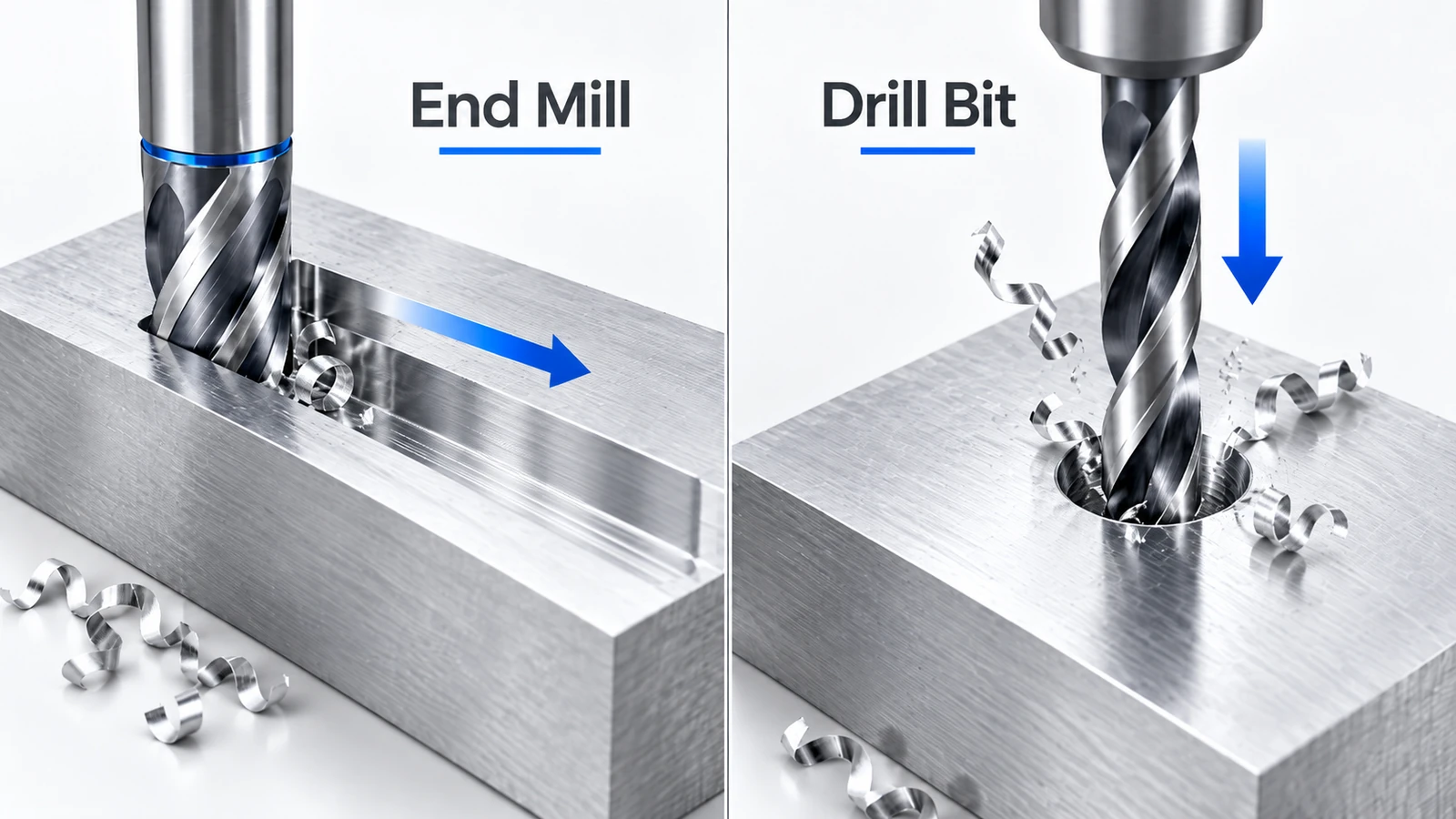
A conventional drill bit is usually more efficient for producing standard holes.
An end mill is more versatile for generating profiles, pockets, shoulders, and complex surfaces.
Although a center-cutting end mill may perform certain axial cutting operations, it should not automatically replace a dedicated drill.
Conclusion
End mills are essential cutting tools for CNC milling operations, including slotting, pocket machining, contouring, and surface finishing.
Different end mill designs serve different purposes. Flat end mills are versatile for general machining, ball nose cutters produce curved surfaces, and corner radius tools provide stronger cutting-edge geometry for suitable applications.
Choosing the correct flute count, tool diameter, material, and cutting geometry helps control cutting forces, chip evacuation, surface finish, and tool life.
For component designers, appropriate internal radii, accessible features, and reasonable machining depths can also improve manufacturing efficiency.
Frequently Asked Questions
Some center-cutting end mills can enter material axially, but their suitability depends on tool geometry and cutting conditions. A dedicated drill is generally more efficient for producing conventional holes.
A flat end mill is primarily used for planar surfaces, slots, and shoulders. A ball nose end mill has a hemispherical tip designed for curved surfaces and three-dimensional contour machining.
No. More flutes provide additional cutting edges but generally reduce chip space for a comparable tool diameter and geometry. The best flute count depends on material, cutting engagement, and chip evacuation.
End mills may break due to excessive cutting forces, poor workholding, excessive overhang, chip packing, unsuitable cutting parameters, or tool wear. Stable machining conditions and appropriate tool selection help reduce breakage.



