

Rivets are permanent mechanical fasteners used to join two or more components without threads. They are widely used in sheet metal, aerospace structures, automotive assemblies, enclosures, machinery, electronics, and construction.
Common rivet types include solid rivets, blind rivets, structural blind rivets, tubular rivets, semi-tubular rivets, split rivets, drive rivets, self-piercing rivets, and flush rivets.
The right rivet depends on several factors, especially joint access, load, material thickness, grip range, corrosion environment, surface requirements, and production volume.
What Is a Rivet?
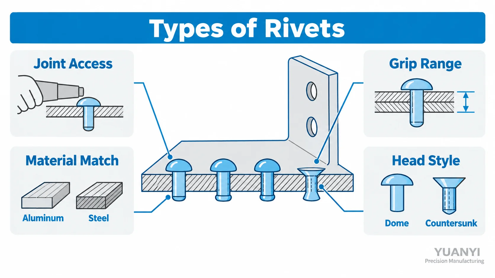
A rivet is a permanent fastener with a head and a shank.
During installation, the rivet passes through aligned holes in the components being joined. The opposite end is then deformed, expanded, or pulled into shape to create a second head or locking feature.
Once installed, the rivet mechanically clamps the parts together.
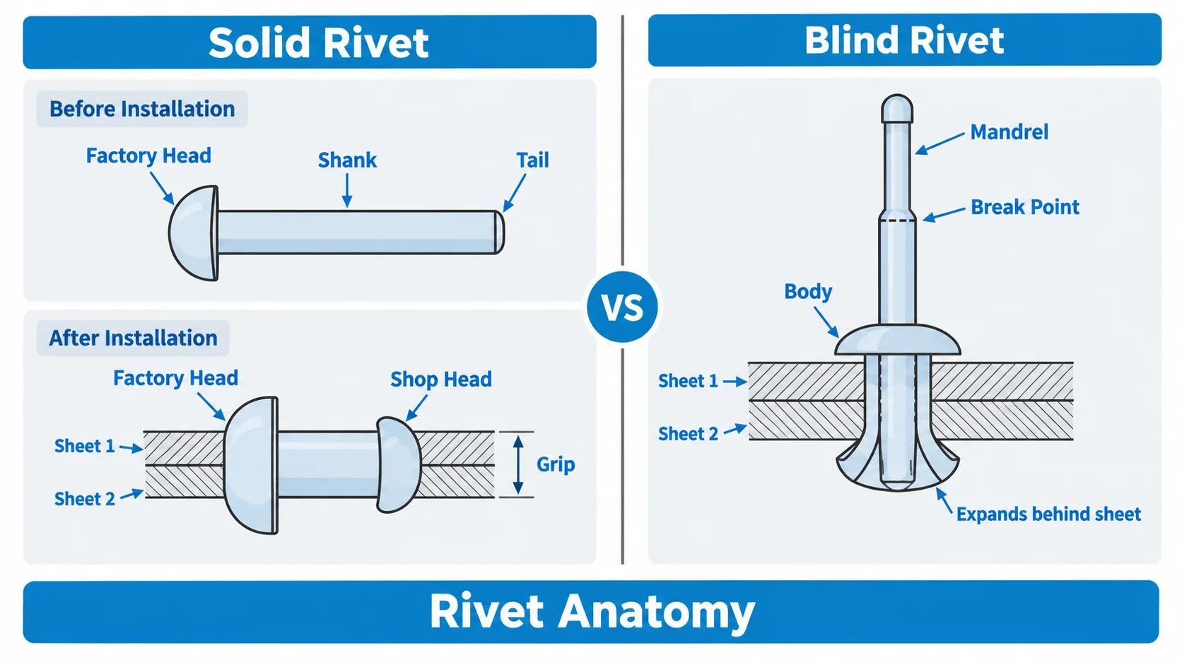
The main parts of a conventional rivet include:
- Factory head — the preformed head
- Shank — the cylindrical body
- Tail — the end that is deformed during installation
- Shop head — the formed head on a solid rivet after installation
Blind rivets work differently because they use a mandrel to expand the rivet body from one accessible side.
Riveted joints are usually not intended to be disassembled. Removing a rivet typically requires drilling, cutting, or otherwise destroying the fastener.
Rivet Terminology
| Term | Meaning |
|---|---|
| Factory head | The head formed on the rivet during manufacture |
| Shop head (formed head) | The second head created during installation |
| Grip | The total thickness of the parts being joined |
| Grip range | The range of grip thicknesses a blind rivet can clamp correctly |
| Body | The hollow sleeve of a blind rivet that expands behind the joint |
| Mandrel (stem) | The pin pulled by the tool to set a blind rivet |
| Edge distance | Distance from the hole center to the edge of the material |
| Pitch | Center-to-center distance between rivets in the same row |
| Countersink | The conical seat that allows a flush head to sit level with the surface |
| Clinch | The flared part of a self-piercing rivet that locks into the lower sheet |
Rivet Types at a Glance
| Rivet Type | Joint Access | Typical Strength | Best For |
|---|---|---|---|
| Solid Rivet | Both sides | High | Aerospace and structural joints |
| Blind Rivet | One side | Medium | Sheet metal and enclosures |
| Structural Blind Rivet | One side | High | Loaded assemblies |
| Tubular Rivet | Usually both sides | Low–Medium | Soft or thin materials |
| Semi-Tubular Rivet | Usually both sides | Medium | Hinges and machinery |
| Split Rivet | One or both sides | Low | Soft materials |
| Drive Rivet | One side | Low–Medium | Panels and light-duty assembly |
| Self-Piercing Rivet | Press access | High | Automotive sheet metal |
| Flush Rivet | Depends on design | Medium–High | Smooth aerodynamic or cosmetic surfaces |
9 Common Types of Rivets
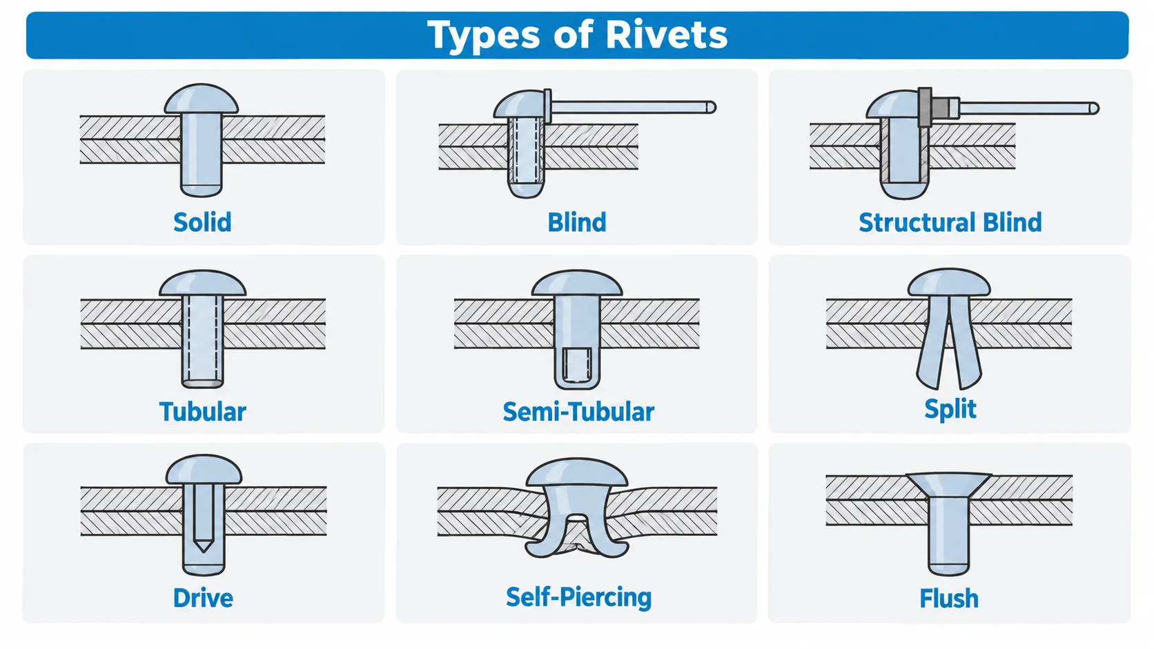
Solid Rivets
Solid rivets are one of the simplest and strongest rivet designs.
They consist of a solid shank with a factory head on one end. During installation, the tail is mechanically deformed to create a second head.
Solid rivets generally require access to both sides of the joint.
Best for: high-strength, fatigue-resistant permanent joints.
Common applications: aircraft structures, bridges, heavy equipment, structural sheet metal, and industrial assemblies.
Because they do not contain an internal mandrel or hollow section, solid rivets can provide excellent strength and durability when properly installed.
Design notes: solid rivets are used in large volumes in airframe work, where the installed head is inspected against defined size limits and the hole is normally drilled 0.05 to 0.15 mm larger than the rivet diameter, depending on the specification.
Blind Rivets
Blind rivets, often called pop rivets, are designed for joints where only one side is accessible.
A blind rivet normally consists of a hollow rivet body and a mandrel. During installation, the rivet tool pulls the mandrel, causing the rivet body to expand behind the material and clamp the joint.
The mandrel then breaks at a controlled point.
Best for: one-sided installation.
Common applications: sheet metal enclosures, cabinets, HVAC equipment, electronics housings, vehicle panels, and general fabrication.
Common blind rivet variants include:
- open-end blind rivets
- closed-end blind rivets
- multi-grip rivets
- structural blind rivets
Design notes: open-end rivets are economical but the mandrel head remains inside the body, so the joint is not sealed. Closed-end rivets form a sealed body and are the usual choice for water or air tightness. Multi-grip rivets cover a wider grip range, which reduces the number of part numbers required.
Structural Blind Rivets
Structural blind rivets are designed to carry higher loads than standard blind rivets.
They usually have stronger bodies and more robust internal locking mechanisms that help retain the mandrel and improve shear and tensile performance.
Best for: high-load joints where only one side is accessible.
Common applications: commercial vehicles, trailers, transportation equipment, industrial enclosures, machinery, and structural sheet metal.
They are especially useful when a conventional solid rivet cannot be installed because rear-side access is unavailable.
Design notes: mechanically locked spindle designs keep the mandrel in place after setting, which is what allows the joint to be treated as structural. In aerospace work, structural blind rivets are specified under NAS series standards and OEM specifications rather than as generic hardware.
Tubular Rivets
Tubular rivets have a partially or fully hollow shank.
The hollow end requires less force to deform than a solid rivet, making tubular rivets suitable for lighter materials and assemblies.
Best for: light-duty joints where lower forming force is beneficial.
Common applications: leather products, plastics, electrical products, small mechanisms, nameplates, and consumer goods.
Tubular rivets are generally not selected for highly loaded structural joints.
Semi-Tubular Rivets
Semi-tubular rivets have a hollow section only near the tail, while most of the shank remains solid.
This design reduces installation force while retaining more strength than a fully tubular rivet.
Best for: medium-duty joints that may also require pivoting movement.
Common applications: hinges, brake systems, ladders, mechanical linkages, casters, and industrial assemblies.
They are often used where the rivet must both fasten components and act as a pivot point. In that case, the hole in the moving part is usually a clearance fit and the rivet shoulder controls the pivot.
Split Rivets
Split rivets have a shank divided into two legs.
During installation, the legs spread apart and grip the material.
They are mainly intended for soft or low-strength materials.
Best for: light-duty fastening in materials that can accept spreading legs.
Common applications: wood, leather, fiberboard, soft plastics, cases, and decorative products.
They are not usually appropriate for high-strength metal-to-metal structural joints.
Drive Rivets
Drive rivets are installed by driving a pin into the rivet body.
As the pin moves inward, the rivet expands and locks into the hole.
Installation is simple and generally requires access from only one side.
Best for: fast installation in light- to medium-duty applications.
Common applications: signs, identification plates, light sheet metal, panels, appliances, and decorative assemblies.
Self-Piercing Rivets
Self-piercing rivets, or SPRs, can join sheet materials without requiring a fully pre-drilled hole.
A press drives the rivet through the upper sheet and into the lower layer, where the rivet flares and mechanically interlocks with the material.
The rivet normally does not completely penetrate the bottom sheet.
Best for: automated high-volume sheet metal assembly.
Common applications: automotive bodies, aluminum vehicle structures, appliance manufacturing, and mixed-material sheet assemblies. The automotive sheet-metal side of this is covered in our automotive machining overview.
Self-piercing riveting is especially useful where welding is difficult or where heat input should be avoided.
Design notes: SPR requires access for both the punch and the die, a rigid press frame, and a die geometry matched to the sheet stack. It is less suitable for thick stacks, high-strength steel, or brittle materials.
Flush Rivets
Flush rivets, also called countersunk rivets, are designed so the rivet head sits level with the surrounding surface.
The workpiece requires a countersunk seat that matches the rivet head geometry.
Best for: joints requiring a smooth external surface.
Common applications: aircraft skins, exterior panels, high-speed vehicles, precision enclosures, and cosmetic assemblies.
Flush riveting can reduce protrusions that may interfere with airflow, moving components, or appearance.
Design notes: the countersink must match the head angle exactly. Airframe rivets normally use a 100° head, while many general-industry countersunk fasteners use 82° or 90°. Airframe practice also prefers a flush head that is slightly shallower than the sheet so the head can be shaved only if required, rather than risking a knife-edge in thin material.
Rivet Materials and Material Compatibility
Rivets are commonly made from aluminum, steel, stainless steel, copper, and brass.
The correct material depends not only on rivet strength but also on the materials being joined.
| Rivet Material | Main Advantage | Typical Use |
|---|---|---|
| Aluminum | Lightweight and corrosion resistant | Aluminum sheet, enclosures |
| Steel | High strength and economical | General structural assembly |
| Stainless Steel | Strength and corrosion resistance | Outdoor, marine, food equipment |
| Copper | Conductive and corrosion resistant | Electrical and decorative uses |
| Brass | Corrosion resistance and appearance | Electrical, decorative applications |
| Monel | High strength with excellent corrosion resistance | Marine, chemical, aerospace |
| Titanium and titanium-niobium | Strength, low weight, compatibility with composites | Aerospace structures, carbon fiber assemblies |
Aluminum Rivets
Aluminum rivets are lightweight and relatively easy to install.
They are common in aluminum panels, sheet metal enclosures, HVAC systems, transportation components, and general fabrication.
Aluminum rivet alloys are not all equivalent. Soft 1100-grade rivets are easy to drive and used for low-load work, while 2117 and 2024 grades are the workhorses of airframe assembly, and 7050 grades are used where higher strength is required. Our aluminum machining page covers the workpiece side of the same material family.
Steel Rivets
Steel rivets provide higher strength than many aluminum rivets and are commonly used in industrial and structural applications.
Surface coatings may be required where corrosion is a concern. Zinc plating, phosphate and zinc-nickel finishes are common. Base material options are described in our carbon steel machining guide.
Stainless Steel Rivets
Stainless steel rivets offer high strength and good corrosion resistance.
They are frequently used in outdoor equipment, marine environments, food-processing machinery, and applications exposed to moisture or chemicals. The same reasoning that drives stainless steel selection for machined parts applies to the rivet.
Note that a stainless rivet installed in aluminum sheet creates a galvanic couple, so isolation or a suitable coating may be required.
Copper and Brass Rivets
Copper and brass rivets are used where conductivity, corrosion resistance, appearance, or compatibility with copper-based materials is important.
They are common in electrical equipment, decorative products, and specialty assemblies. See our copper and brass machining pages for the equivalent workpiece materials.
Nickel, Monel and Titanium Rivets
Monel rivets provide high strength together with excellent corrosion resistance, and they are widely used in marine, chemical, and aerospace applications where aluminum or steel rivets would not last. Nickel-based materials are covered on our nickel alloys page.
Titanium and titanium-niobium rivets are used in aerospace structures, particularly where carbon fiber composites are involved, because titanium is much more compatible with carbon fiber than aluminum is. They are also lighter than steel or Monel at comparable strength.
Watch for Galvanic Corrosion
Rivet material should be selected together with the joined materials.
When dissimilar metals are electrically connected in the presence of moisture or an electrolyte, galvanic corrosion can occur.
For example, combining certain stainless steel fasteners with aluminum in a wet environment may accelerate corrosion of the aluminum.
Material selection may therefore require:
- compatible rivet and sheet materials
- protective coatings
- sealants
- washers or isolating layers
- environmental protection
As a rule, the further apart two metals sit in the galvanic series, the faster the less noble metal will corrode when an electrolyte is present. Aluminum, carbon steel, stainless steel, copper alloys, and titanium sit at very different positions, which is why mixed-material joints deserve a specific review.
Material Choice and Machined Hardware
The rivet and the parts it joins are a single system. Sheet material, machined bracket material, coating, and rivet material should be selected together, and the same galvanic and thermal-expansion questions apply to all three. A broader view of material options is available in our material selection guide.
Rivet Standards and Specifications
Rivets are specified by standard, because the standard fixes the head geometry, dimensions, material, and performance requirements that the joint design depends on. Two rivets that look identical can be completely different in shear strength and grip behavior.
| Standard | What It Covers |
|---|---|
| AN426 / MS20426 | 100° countersunk head solid rivets used in airframe work |
| AN470 / MS20470 | Universal head solid rivets used in airframe work |
| NAS1097 | Reduced (undersized) head countersunk rivets for thin sheets and tight spacing |
| DIN 7337 | Blind rivets for general industrial use |
| IFI-114 | Blind rivet standard used in North America |
| ISO 15977 to ISO 15984 | Open-end and closed-end blind rivets with break pull mandrel, covering several body and mandrel material combinations |
| NAS series and OEM specifications | Structural blind rivets used in aerospace assemblies |
| Material standards | ASTM, AMS, and ISO standards for rivet wire and body materials |
In practice, a complete rivet callout should define at least: standard and part number, body material and finish, diameter, head style, grip range or length, and any sealing requirement. For structural joints, the acceptance criteria for the installed rivet should also be defined before production starts.
Rivet Size, Grip Range, and Head Style
Choosing the rivet type is only part of the selection process.
Rivet diameter, length, grip range, hole size, and head style must also match the joint.
Rivet diameter
Rivet diameter affects joint strength and required hole size.
Larger rivets can generally carry higher loads, but they also require more space and larger holes.
The required diameter should be based on load, material thickness, edge distance, and the relevant rivet specification.
Rivet length
Rivet length must provide enough material to correctly form the tail or locking section after passing through the joint.
A rivet that is too short may not form correctly, while an excessively long rivet can create poor clamping or an oversized shop head.
Grip range
Grip range is especially important for blind rivets.
Grip thickness = total thickness of all materials being joined. For example, sheet 1 thickness plus sheet 2 thickness equals the total grip thickness.
The selected rivet must have a grip range that includes that total thickness. A rivet outside the correct grip range may not clamp the joint correctly.
Hole diameter
Hole size depends on the rivet design, diameter, installation method, and relevant fastener specification.
It should follow the rivet manufacturer’s recommended hole size or the applicable engineering standard. Using excessive clearance can reduce joint quality, while an undersized hole may prevent proper installation.
Head style
Common rivet head styles include dome head, large flange head, countersunk head, flat head, and specialty structural heads.
| Head Style | Characteristic | Typical Use |
|---|---|---|
| Dome (button) head | Standard protruding head, simple and strong | General sheet metal and structure |
| Large flange head | Spreads load over a wider area | Soft or thin material, plastics |
| Countersunk (flush) head | Sits level with the surface | Aircraft skins, visible surfaces |
| Flat head | Low profile, moderate bearing area | Light-duty panels and plates |
| Reduced head | Smaller head diameter for tight spacing | Thin sheets and close-pitch rows |
Where a flush surface is required, the seat is normally produced by machining or countersinking. The differences between a countersink and a counterbore, and where each is appropriate, are explained in our guide to counterbore vs countersink.
Riveted Joint Design Rules
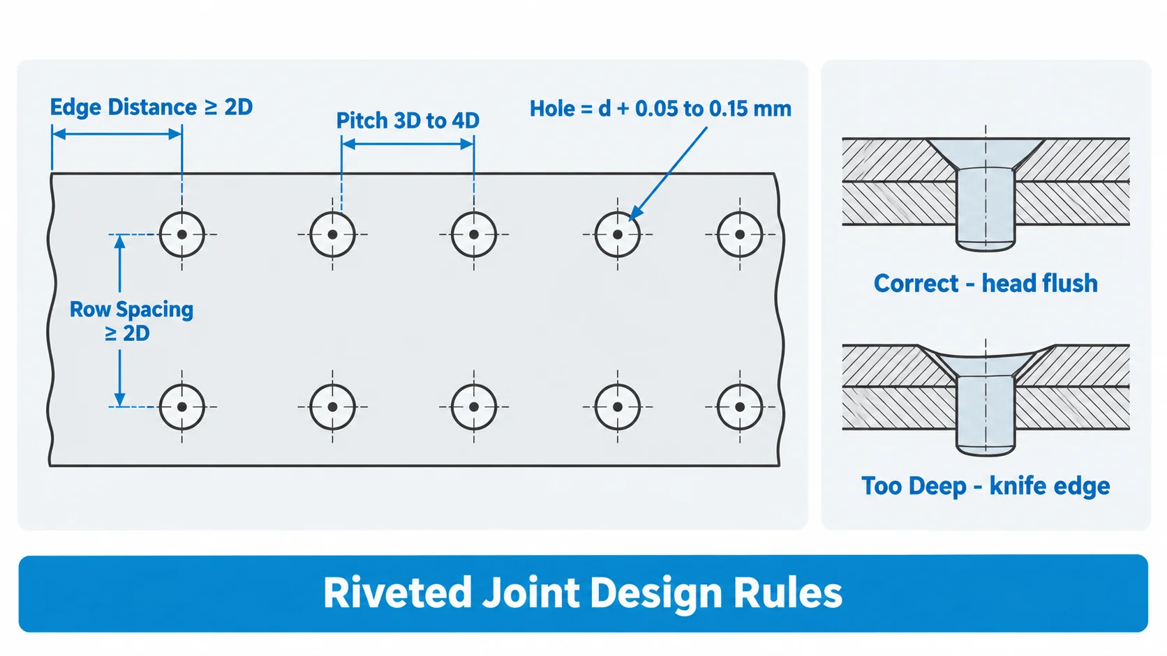
Most riveted joint problems come from the hole, edge distance, or spacing rather than from the rivet itself. The following values are common rules of thumb used in sheet metal and airframe work; they must always be confirmed against the applicable specification or drawing.
| Rule | Typical Value | Why It Matters |
|---|---|---|
| Hole size | About 0.05 to 0.15 mm larger than the rivet diameter | Too much clearance reduces joint strength; too little prevents installation |
| Minimum edge distance | About 2 times the rivet diameter, center to edge | Prevents the sheet from tearing out at the edge |
| Rivet pitch | Roughly 3 to 4 times the rivet diameter in structural joints | Controls load sharing between rivets and the buckling of the sheet between them |
| Row spacing | At least about 2 times the rivet diameter between rows | Avoids overlapping stress fields and distortion |
| Countersink depth | Flush head level with the surface, without leaving a knife edge | A deep countersink in thin sheet weakens the joint |
| Minimum sheet thickness | Use a reduced-head rivet for very thin sheet | A full-size countersunk head may not have enough material to sit in |
| Hole quality | Deburred, round, and aligned | Burns and out-of-round holes prevent clamping and start fatigue cracks |
| Sealing | Closed-end rivets or sealant where tightness is required | Open-end rivets do not seal, so leaks develop |
Hole alignment is often the hardest part to control on a real assembly. Matching parts by drilling or reaming them while clamped together, and using machined fixtures or jigs, is usually the most reliable way to keep holes concentric across several layers.
Rivet Installation Methods and Tools
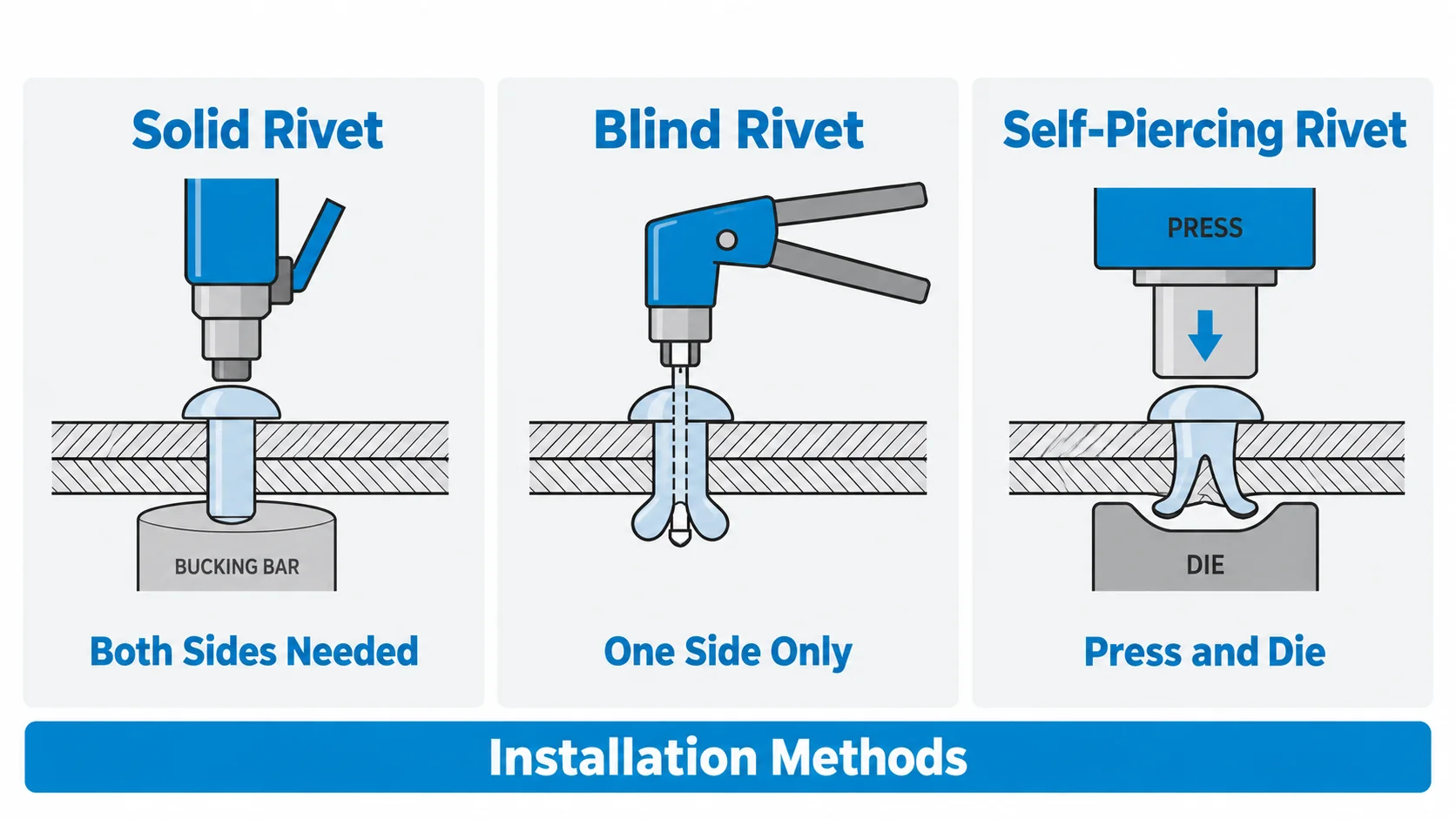
Installation method has to be chosen with the rivet type, because it determines the tooling, the setting force, and the access needed at the joint.
Solid rivets are set with a rivet gun and a bucking bar, a squeeze riveter, or a C-frame press. Manual gun-and-bar work needs access to both sides and a skilled operator, while squeeze riveting gives more consistent results in a fixture.
Blind rivets are set with a hand, pneumatic, or battery-powered tool. The tool pulls the mandrel until it breaks at the designed load, so the setting force and the grip range must match the rivet.
Drive rivets are set by driving the pin in with a hammer or press, which is why they are common for panels and signs on site.
Self-piercing rivets are set in a press with a matched punch and die. Setting force, die geometry, and sheet stack are all critical, and the process is normally qualified and monitored in production.
Higher volume assembly often uses automated or semi-automated riveting equipment, while repair work is still largely manual.
How to Inspect a Riveted Joint
Inspection should confirm that the rivet was installed within its design intent.
Points to check include:
- the formed head is the correct size and shape for the rivet type
- the head is not under-driven, cracked, or tilted
- the joint is tight, with no visible gap between the sheets
- the mandrel of a blind rivet is retained, or broken at the intended point
- the sheet around the rivet is not distorted, buckled, or torn
- the rivet has not been over-driven, which thins the sheet and can crack it
As a rule of thumb used in airframe work, a well-formed shop head ends up about 1.5 times the rivet diameter across and about half the rivet diameter high. For structural or safety-related joints, the acceptance criteria and inspection method should be defined by the applicable standard rather than by shop habit.
How to Remove a Rivet
Rivets are permanent fasteners, so removal always damages the rivet.
The usual approach for a solid rivet is to center-punch the head, drill with a bit slightly smaller than the rivet diameter until the head is removed or nearly removed, and then push the remaining shank out with a pin punch. The depth must be controlled to avoid enlarging the hole in the sheet.
For a blind rivet, drilling through the head is usually enough to release the body, after which the remainder can be punched out. In both cases the surrounding surface should be protected, and the hole should be inspected afterwards before a replacement rivet is installed.
How to Choose the Right Rivet
A practical rivet selection process should begin with the joint conditions.
1. Check joint access
If only one side is accessible, a blind rivet or structural blind rivet is usually the most practical choice. If both sides are accessible and high structural strength is required, a solid rivet may be more suitable.
2. Determine the required strength
Consider tensile load, shear load, vibration, fatigue, and shock. Light-duty assemblies may use tubular, split, or standard blind rivets, while higher-load joints may require solid rivets, structural blind rivets, or self-piercing rivets. The rivet should always be selected using actual engineering load requirements rather than appearance alone.
3. Check material thickness
Measure the total thickness of the joint. For blind rivets, make sure this value falls inside the specified grip range. For solid and tubular rivets, the rivet length must provide enough material to form the final head correctly.
4. Check material compatibility
Match rivet material with the joined materials and environment, considering corrosion, galvanic compatibility, mechanical strength, temperature, conductivity, and appearance.
5. Consider surface requirements
If the fastener must not protrude above the surface, use a flush or countersunk rivet where appropriate. If load distribution is more important, a larger flange head may be better.
6. Consider production volume
For occasional repair or low-volume assembly, hand or pneumatic blind rivet tools may be adequate. For high-volume automotive sheet metal production, automated self-piercing riveting can provide much higher throughput.
7. Select diameter, length, and head style
After choosing the rivet family, confirm rivet diameter, joint thickness, grip range, hole size, head geometry, material grade, and installation tool.
8. Verify on a sample or first article
Set the rivet in a sample of the real material stack, inspect the formed head, and confirm clamping and hole quality before running the full batch. Where the rivet works with a machined part, check the machined dimensions in the same review.
Quick Rivet Selection by Application
| Requirement | Typical Rivet Choice |
|---|---|
| Access from one side only | Blind rivet |
| High structural load with two-side access | Solid rivet |
| High load with one-side access | Structural blind rivet |
| Thin or soft materials | Tubular / semi-tubular rivet |
| Automated sheet metal joining | Self-piercing rivet |
| Smooth exterior surface | Flush rivet |
| Light-duty soft material | Split rivet |
| Fast installation of panels or signs | Drive rivet |
Rivets vs Screws vs Welding
Riveting is only one way to join components.
| Joining Method | Removable | Heat Required | One-Side Installation | Main Advantage |
|---|---|---|---|---|
| Rivet | No | No | Some types | Fast permanent fastening |
| Screw | Yes | No | Depends on design | Easy maintenance |
| Welding | No | Yes | Depends | Continuous metal joint |
Rivets are particularly useful when:
- heat from welding is undesirable
- vibration resistance is important
- access is limited
- thin sheets must be joined
- mixed materials are involved
- permanent mechanical fastening is acceptable
Threaded fasteners are usually better when regular disassembly is required, while welding may be preferable where a continuous structural or sealed metal joint is needed.
Failure Modes of Riveted Joints
Riveted joints usually fail through the joint rather than through the rivet body alone. Knowing the failure modes helps set the design and inspection priorities.
| Failure Mode | What Happens | Typical Cause |
|---|---|---|
| Rivet shear | The rivet is cut across the shank | Joint under-designed in shear; too few rivets |
| Sheet tear-out | The sheet fails between the hole and the edge | Edge distance too small |
| Bearing failure and hole elongation | Holes become oval and the joint loosens | Thin sheet, high load, oversized holes |
| Pull-through | The head pulls through the sheet | Thin sheet with a small head; use a large flange or washer |
| Fatigue cracking | Cracks start at holes and grow under cyclic load | High cyclic stress, poor hole quality, no interference or preload |
| Fretting | Surfaces rub where the joint works loose | Under-driven rivets and insufficient clamping |
| Galvanic corrosion | Dissimilar metals corrode at the joint | Incompatible material pair in a wet environment |
| Installation defects | Under-driven, cracked, or tilted heads; lost mandrels | Wrong tool, wrong grip range, poor access |
Most of these modes are addressed by the same three things: correct hole size and quality, sufficient edge distance and pitch, and a rivet that actually clamps the stack in its specified grip range.
CNC Machined Parts Used in Riveted Assemblies
Standard rivets are usually manufactured by forming, heading, or related high-volume fastener processes rather than CNC machining.
However, riveted assemblies frequently include CNC-machined components such as:
- brackets
- housings
- frames
- mounting plates
- spacers
- bushings
- supports
- precision panels
The dimensions of these components can affect hole alignment, edge distance, countersink geometry, joint fit, and final assembly accuracy.
For assemblies using flush rivets, countersink dimensions are especially important because the head must seat correctly without weakening the surrounding material.
| Machined Feature | Effect on the Riveted Joint |
|---|---|
| Hole diameter and location | Sets joint fit and hole-to-hole alignment across layers |
| Counterbore or countersink depth | Determines whether a flush head sits level without a knife edge |
| Edge distance at machined edges | Controls tear-out resistance |
| Face flatness and thickness | Determines clamping and stack height |
| Deburring of holes | Prevents poor clamping and fatigue crack initiation |
| Hole position tolerance in a pattern | Allows a common drilling or riveting setup |
These features are machined by CNC milling, CNC turning, and, for housings with features on several faces, 5-axis machining. Because hole patterns and countersink depths are usually tight, they are normally specified with the appropriate CNC machining tolerances and verified before assembly.
For new products, machined brackets and panels are often produced as working prototype parts so that hole alignment, rivet grip, and joint tightness can be proven before tooling or volume production is committed. Dimensional inspection of these features is normally covered under quality assurance procedures.
Conclusion
The most common rivet types include solid, blind, structural blind, tubular, semi-tubular, split, drive, self-piercing, and flush rivets.
Each is suited to different joint conditions.
A blind rivet is useful when only one side is accessible, a solid rivet is well suited to high-strength structural joints, a self-piercing rivet supports automated sheet metal assembly, and a flush rivet is useful when a smooth surface is required.
When selecting a rivet, focus on joint access, load, total material thickness, grip range, material compatibility, environment, surface requirements, and production volume.
The right rivet is not simply the one that fits the hole. It must form correctly, clamp the joint securely, withstand the required loads, and remain compatible with the surrounding materials throughout the intended service life.
At YUANYI Precision Manufacturing, we machine the brackets, housings, frames, panels, and spacers that riveted assemblies are built on, and we control hole location, countersink depth, and edge distance as part of the same tolerance review.
Have a riveted assembly that needs precision machined components? Send us your drawing for a DFM review and quotation.
Frequently Asked Questions
Common rivet types include solid rivets, blind rivets, structural blind rivets, tubular rivets, semi-tubular rivets, split rivets, drive rivets, self-piercing rivets, and flush rivets.
A solid rivet normally requires access to both sides of the joint because its tail must be mechanically formed. A blind rivet can be installed from only one side using a mandrel.
Grip range is the range of total material thickness that a blind rivet can properly clamp. The combined thickness of all joined layers should fall within the rivet’s specified grip range.
A blind rivet is commonly used when only one side of the joint is accessible. If higher structural strength is required, a structural blind rivet may be more appropriate.
Solid rivets are widely used for high-strength structural joints, while structural blind rivets can provide high strength where only one side is accessible. The correct choice depends on material, diameter, joint design, shear load, tensile load, and installation quality.
They can under certain environmental conditions. Galvanic corrosion may occur when dissimilar metals are electrically connected in the presence of moisture or another electrolyte. Rivet and workpiece materials, coatings, isolation methods, and service environment should therefore be considered together.
As a rule of thumb, a solid rivet hole is drilled about 0.05 to 0.15 mm larger than the rivet diameter, and blind rivets follow the manufacturer’s recommended hole size for that specific part. Excessive clearance reduces joint strength, while an undersized hole makes installation impossible or damages the coating.
Typical practice is an edge distance of at least about 2 times the rivet diameter from hole center to edge, a pitch of roughly 3 to 4 times the rivet diameter in structural joints, and at least about 2 times the diameter between rows. These values are set by the applicable specification, so they should always be confirmed against the drawing or standard.
Check that the formed head is the correct size and shape, that the joint has no gap, that the sheet is not distorted, and that a blind rivet mandrel is retained or broken as intended. A common airframe rule of thumb is a shop head about 1.5 times the rivet diameter across and about half the diameter high.
For the same diameter in shear, a correctly installed solid rivet generally outperforms a screw in a permanent structural joint because the shank fills the hole completely. Screws are chosen when disassembly is required, or when clamping load rather than shear strength is the priority.
Center-punch the head, drill with a bit slightly smaller than the rivet diameter, control the depth so the sheet is not enlarged, then push the remaining shank out with a pin punch. Blind rivets are usually released by drilling through the head. Always inspect the hole before installing a replacement rivet.
Open-end blind rivets leave the mandrel head inside a hollow body, so the joint is not sealed. Closed-end blind rivets form a sealed body, which is why they are used where water or air tightness matters, such as tanks, marine parts, and outdoor enclosures.



