

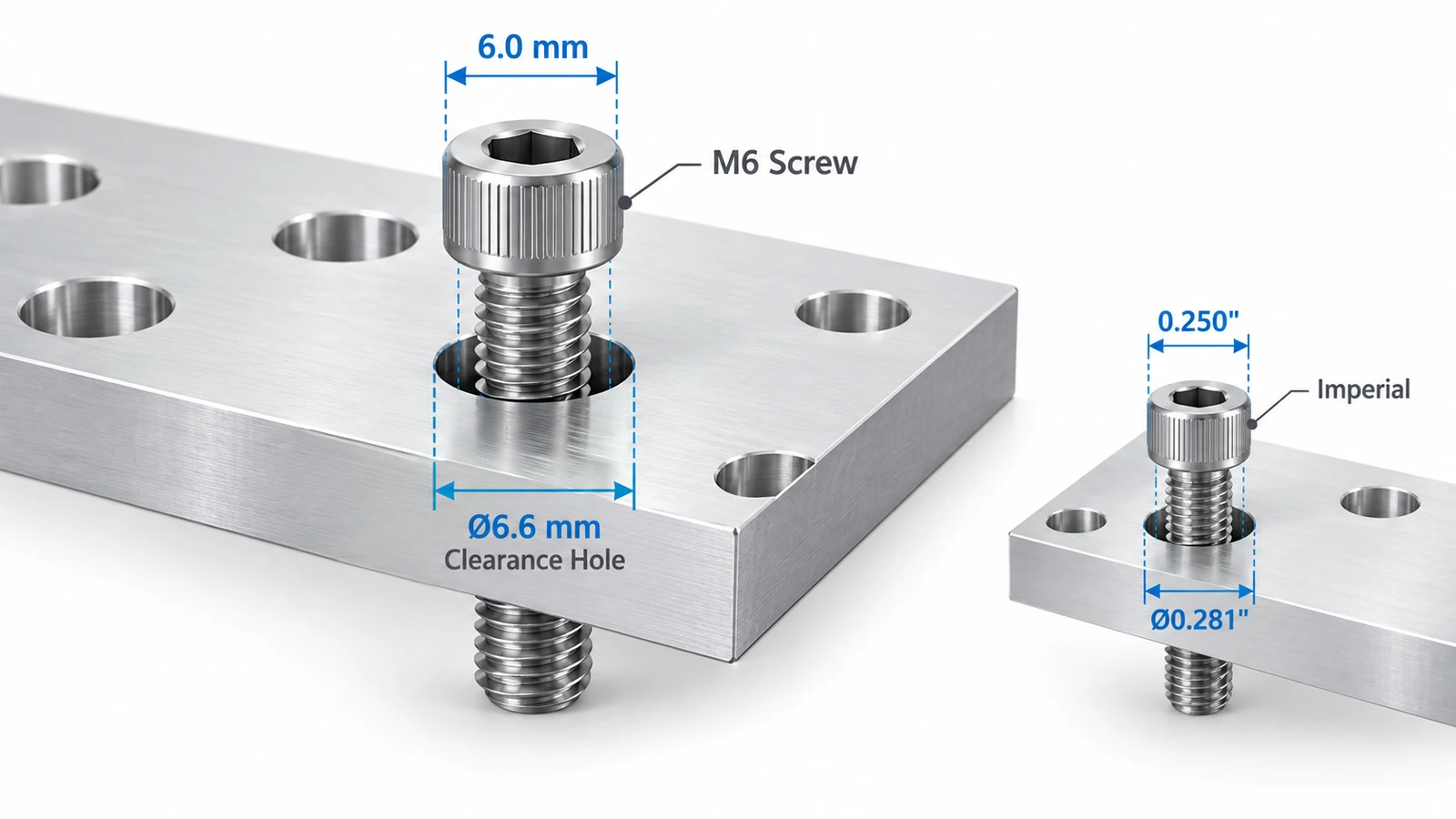
A clearance hole is an unthreaded hole slightly larger than a screw or bolt, allowing the fastener to pass through without engaging the material. The correct hole size depends on the fastener diameter, required assembly clearance, and applicable standard.
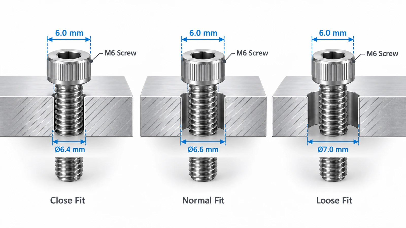
For example, an M6 screw commonly uses a 6.4 mm close-clearance hole, a 6.6 mm normal-clearance hole, or a 7.0 mm loose-clearance hole under ISO 273.
The metric and imperial clearance hole size charts below provide quick dimensions, followed by practical guidance for choosing the right fit and avoiding CNC machining and assembly problems.
Metric Clearance Hole Size Chart (ISO 273)
ISO 273 provides three general-purpose clearance-hole series for metric bolts and screws: fine, medium, and coarse. These are commonly described as close, normal, and loose clearance.
All dimensions below are nominal hole diameters in millimeters.
| Screw Size | Close / Fine (mm) | Normal / Medium (mm) | Loose / Coarse (mm) |
|---|---|---|---|
| M2 | 2.2 | 2.4 | 2.6 |
| M2.5 | 2.7 | 2.9 | 3.1 |
| M3 | 3.2 | 3.4 | 3.6 |
| M4 | 4.3 | 4.5 | 4.8 |
| M5 | 5.3 | 5.5 | 5.8 |
| M6 | 6.4 | 6.6 | 7.0 |
| M8 | 8.4 | 9.0 | 10.0 |
| M10 | 10.5 | 11.0 | 12.0 |
| M12 | 13.0 | 13.5 | 14.5 |
| M14 | 15.0 | 15.5 | 16.5 |
| M16 | 17.0 | 17.5 | 18.5 |
| M18 | 19.0 | 20.0 | 21.0 |
| M20 | 21.0 | 22.0 | 24.0 |
| M22 | 23.0 | 24.0 | 26.0 |
| M24 | 25.0 | 26.0 | 28.0 |
Reference: ISO 273 general-purpose metric clearance-hole series. These are nominal diameters, not complete hole tolerance specifications.
Common Metric Clearance Hole Sizes
For general-purpose assemblies, the medium series is often a practical starting point.
- M3 clearance hole: 3.4 mm
- M4 clearance hole: 4.5 mm
- M5 clearance hole: 5.5 mm
- M6 clearance hole: 6.6 mm
- M8 clearance hole: 9.0 mm
- M10 clearance hole: 11.0 mm
- M12 clearance hole: 13.5 mm
These dimensions provide clearance around the fastener shank, but they do not guarantee correct alignment between multiple mating holes.
If an assembly contains several screws, hole position tolerances and the manufacturing accuracy of both parts must also be considered.
Imperial Clearance Hole Size Chart (Inch Screws)
For inch-series fasteners, ASME B18.2.8 provides close, normal, and loose clearance-hole categories.
The following table shows commonly used drill diameters associated with these clearance categories.
| Screw Size | Close (in) | Normal (in) | Loose (in) |
|---|---|---|---|
| #2 | 0.0938 | 0.1015 | 0.1160 |
| #4 | 0.1200 | 0.1285 | 0.1440 |
| #6 | 0.1540 | 0.1695 | 0.1850 |
| #8 | 0.1800 | 0.1960 | 0.2130 |
| #10 | 0.2055 | 0.2210 | 0.2380 |
| 1/4″ | 0.2656 | 0.2813 | 0.2969 |
| 5/16″ | 0.3281 | 0.3438 | 0.3594 |
| 3/8″ | 0.3906 | 0.4063 | 0.4219 |
| 1/2″ | 0.5313 | 0.5625 | 0.6094 |
| 5/8″ | 0.6563 | 0.6875 | 0.7344 |
| 3/4″ | 0.7813 | 0.8125 | 0.9063 |
| 1″ | 1.0313 | 1.0938 | 1.1563 |
Reference: Common drill-size selections for inch-series clearance holes using ASME B18.2.8 clearance categories. Displayed diameters are rounded drill sizes and should not be interpreted as the full standard hole-size limits.
Metric vs Imperial Clearance Hole Sizes
Metric and imperial clearance holes should be selected independently rather than converted directly between measurement systems.
For example:
- An M6 screw has a nominal diameter of 6.0 mm.
- A 1/4-inch screw has a nominal diameter of 6.35 mm.
Although these fasteners are similar in size, their clearance-hole recommendations are different.
Always identify the actual fastener specification and use the corresponding size chart.
What Is a Clearance Hole?
A clearance hole is a hole without internal threads that allows a screw, bolt, or stud to pass through a component.
In a typical mechanical assembly, the fastener passes through a clearance hole in one part and engages a threaded hole or nut in another.
For example, a CNC-machined aluminum mounting bracket may contain four clearance holes for M6 screws. The screws pass through the bracket and engage threaded holes in a steel machine frame.
The bracket itself does not need internal threads.
Unlike precision locating holes, clearance holes are primarily intended to allow fastener installation. They should not automatically be used to control the exact position of one component relative to another.
Close vs Normal vs Loose Clearance Holes
The difference between close, normal, and loose clearance is the available space between the fastener shank and the hole wall.
A smaller hole does not necessarily produce a better assembly.
| Clearance Type | Characteristics | Typical Use |
|---|---|---|
| Close / Fine | Small clearance, greater sensitivity to misalignment | Accurately manufactured assemblies |
| Normal / Medium | Balanced clearance and assembly flexibility | General brackets, housings, and mounting plates |
| Loose / Coarse | More space for installation and alignment variation | Assemblies requiring greater clearance |
Close Clearance
Close-clearance holes provide relatively little space around a fastener.
For an M6 screw, the ISO 273 fine-series hole is 6.4 mm.
This can be useful when the mating hole positions are accurately controlled. However, even small positional errors may make assembly difficult.
Close clearance should not be confused with a precision fit such as H7, nor should it replace dedicated locating features.
Normal Clearance
Normal clearance offers a balance between installation convenience and hole size.
For example, an M6 screw commonly uses a 6.6 mm normal-clearance hole.
This is often a reasonable starting point for CNC-machined brackets and general industrial equipment where the fastener provides clamping rather than precise positioning.
Loose Clearance
Loose-clearance holes provide additional space for fastener installation.
For an M6 screw, the ISO 273 coarse-series hole is 7.0 mm.
This may help accommodate assembly variation, but excessive clearance can reduce the available bearing area beneath the screw head or washer.
The joint should be checked for suitable bearing support and structural performance.
How to Choose the Right Clearance Hole Size
Selecting the correct clearance hole involves more than matching a screw diameter to a chart.
The hole must accommodate the fastener and allow the complete assembly to function correctly.
1. Identify the Actual Fastener
Start with the specified fastener standard, nominal diameter, and head style.
For example, an M8 fastener may use an 8.4, 9.0, or 10.0 mm clearance hole depending on the required series.
For general-purpose clearance holes, nominal fastener diameter is the primary reference. Thread pitch normally does not change the recommended hole series.
2. Choose the Clearance Category
Use normal clearance as a starting point for many ordinary assemblies.
Consider close clearance when hole positioning is well controlled and there is a functional reason to minimize space around the fastener.
Loose clearance may be appropriate when greater assembly flexibility is needed.
However, the final choice should account for fastener dimensions, material thickness, clamping requirements, and manufacturing tolerances.
3. Check the Complete Hole Pattern
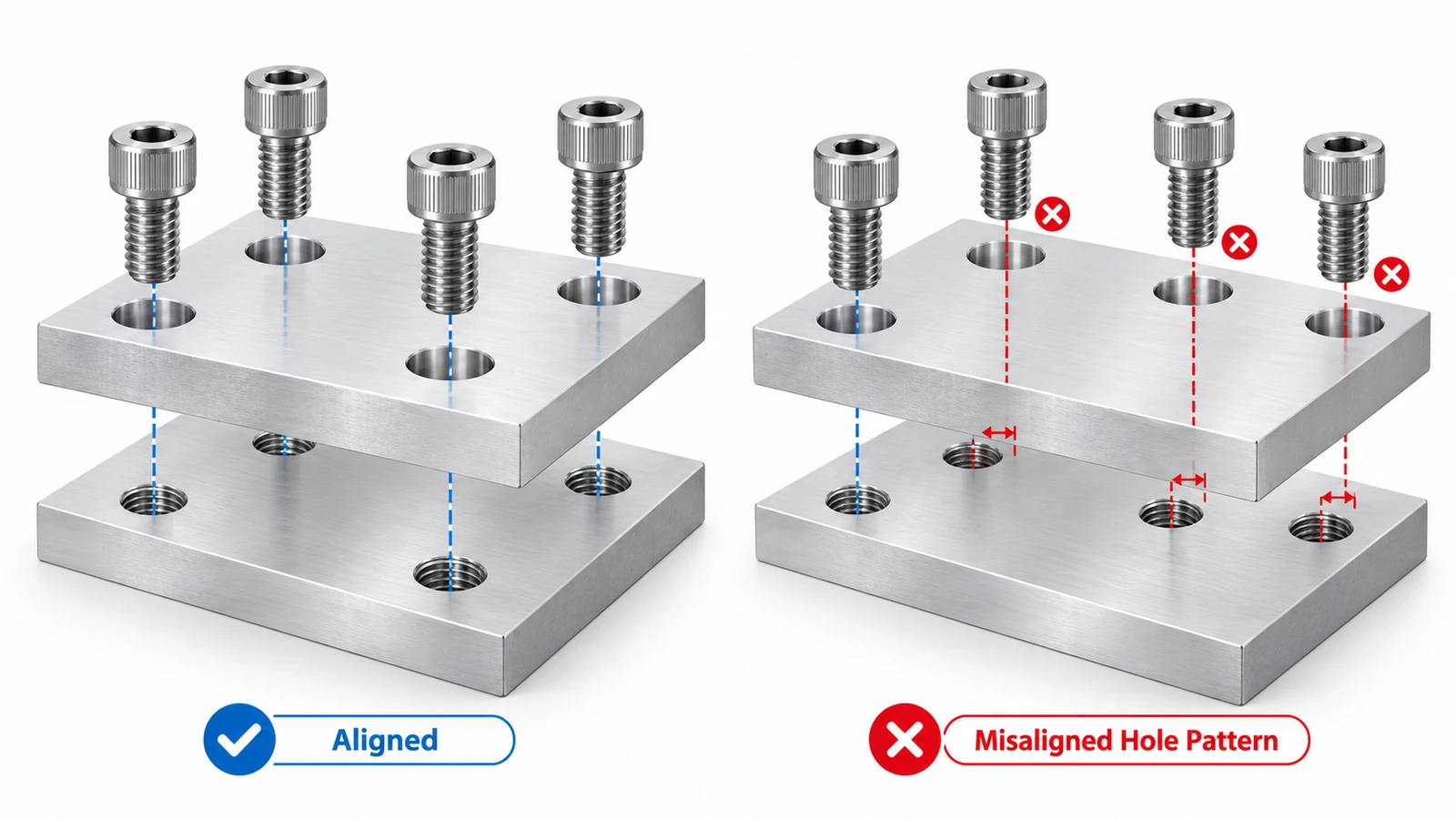
Consider a CNC-machined aluminum mounting plate secured to a machine frame using four M6 screws.
The aluminum plate has four Ø6.6 mm clearance holes. The machine frame contains four corresponding threaded holes.
On paper, the clearance-hole diameters may be correct. However, the assembly can still fail if the two hole patterns are misaligned.
The nominal diametral clearance for a 6.0 mm screw in a 6.6 mm hole is:
6.6 − 6.0 = 0.6 mm
When perfectly centered, this represents a nominal radial clearance of:
0.6 ÷ 2 = 0.3 mm
This does not mean that every hole can independently have 0.3 mm of positioning error.
Actual assembly depends on fastener size variation, hole size tolerances, mating-part location errors, and the simultaneous alignment of all four holes.
If accurate repeatable positioning is required, dowel pins or other dedicated locating features may be preferable.
4. Consider the Material and Final Finish
Material properties can affect the final clearance-hole dimensions.
Aluminum, stainless steel, and engineering plastics have different manufacturing and thermal characteristics.
Surface treatments may also change the effective opening.
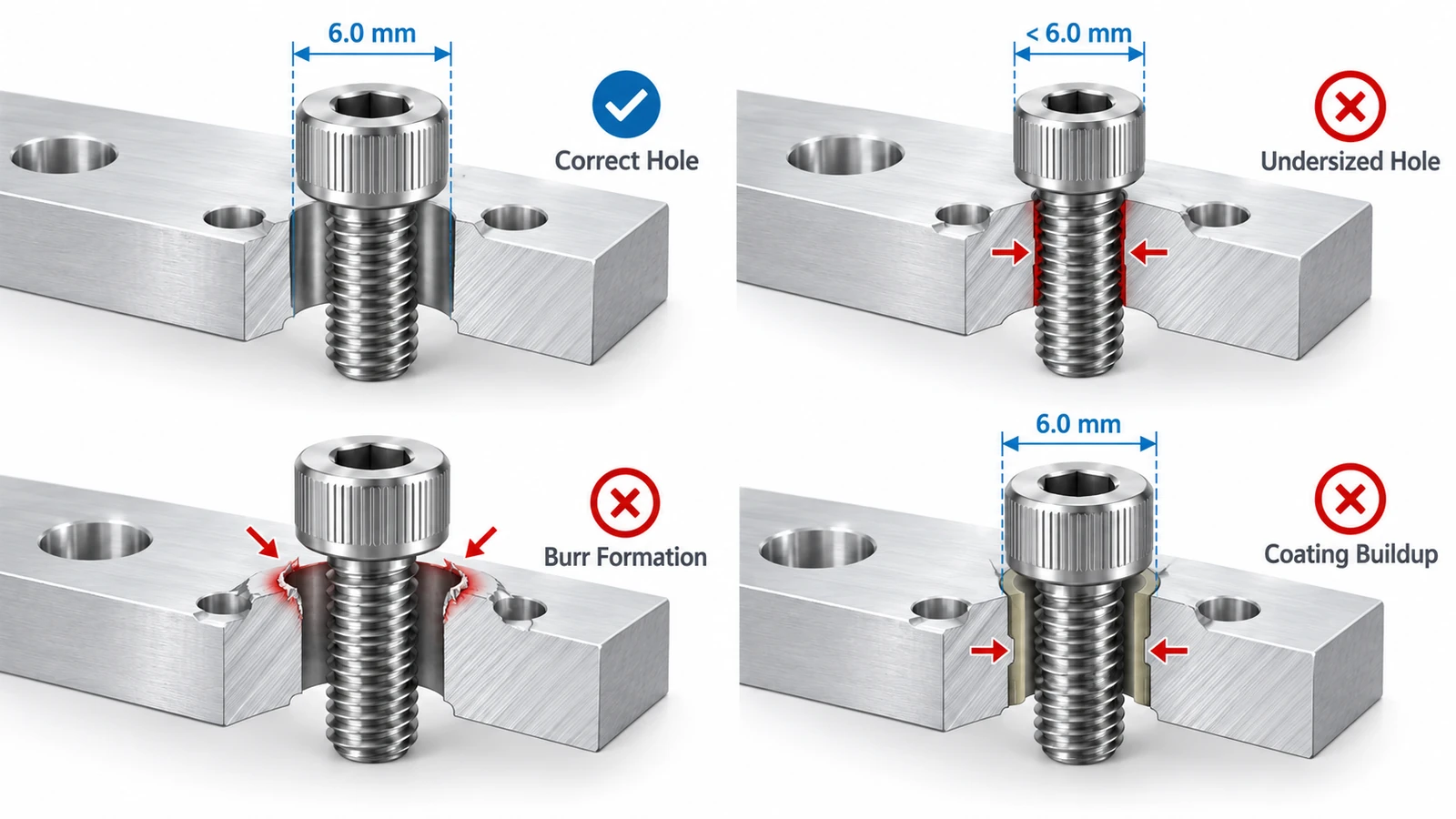
For example, coating buildup inside a hole can reduce its usable diameter. Burrs left by drilling may also interfere with fastener insertion.
The required clearance should therefore be evaluated in the final assembled condition.
CNC Machining Tolerances and Assembly Considerations
Clearance holes are relatively simple CNC features, but reliable fastening requires control over both hole dimensions and hole locations.
Hole Diameter Tolerances
A nominal Ø6.6 mm hole does not automatically define the full acceptable size range.
The engineering drawing should establish the applicable general tolerance or a specific hole tolerance.
For ordinary brackets, unnecessarily tight tolerances may increase manufacturing and inspection costs without providing a functional benefit.
Critical joints may require narrower tolerances or additional inspection requirements.
Hole Position and Alignment
For multi-hole assemblies, positional accuracy can be more important than a small difference in diameter.
A four-hole plate may contain four correctly sized holes yet still fail to assemble because the hole centers do not match the mating component.
Where necessary, designers can use GD&T position tolerances and appropriate datums to control the hole pattern.
Burrs and Edge Conditions
Drilling often creates burrs at the entrance or exit of a hole.
These burrs can obstruct fastener installation or prevent mating surfaces from contacting properly.
A controlled deburring operation or small edge break usually improves assembly reliability.
However, excessive chamfering may reduce the effective bearing surface beneath a screw head or washer.
Choosing the Machining Method
Standard clearance holes are commonly produced by drilling.
For nonstandard diameters or particular geometric requirements, CNC milling and circular interpolation may be suitable alternatives.
The selected method should consider material, hole depth, required accuracy, tool access, and production quantity.
Clearance Hole vs Tapped Hole
A clearance hole and a tapped hole serve different functions in a mechanical assembly.
A clearance hole allows the fastener to pass through, while a tapped hole contains internal threads that engage the screw.
| Feature | Clearance Hole | Tapped Hole |
|---|---|---|
| Primary function | Fastener passage | Thread engagement |
| Internal threads | No | Yes |
| Diameter | Larger than nominal screw diameter | Smaller pilot hole before threading |
| Common operations | Drilling or milling | Drilling followed by tapping or thread milling |
| M6 example | Ø6.6 mm normal clearance | Ø5.0 mm common tap drill for M6 × 1.0 |
A tapped hole requires the correct pilot-hole diameter and threading operation.
For drill-size conversions and thread preparation, see our Complete Drill Size Chart.
If the fastener head must sit flush with or below the surface, an additional counterbore or countersink may be required.
Conclusion
The correct clearance hole must provide enough space for reliable fastener installation while preserving the functional requirements of the joint.
For metric screws, ISO 273 provides fine, medium, and coarse clearance-hole series. For inch-series fasteners, ASME B18.2.8 provides corresponding clearance categories.
Normal clearance is a practical starting point for many general mechanical assemblies, but the final hole dimensions should account for positional accuracy, material behavior, manufacturing tolerances, and the complete fastened joint.
Need CNC-machined components with accurate hole sizes and mounting patterns?
YUANYI provides custom CNC milling and drilling services for aluminum, stainless steel, and engineering plastic parts. Send us your engineering drawings or CAD files to request a quotation and manufacturability review.
Frequently Asked Questions
The common ISO 273 dimensions are 6.4 mm for fine clearance, 6.6 mm for medium clearance, and 7.0 mm for coarse clearance. The medium series is often appropriate for general fastening applications.
An M8 screw typically uses an 8.4 mm fine-clearance hole, a 9.0 mm medium-clearance hole, or a 10.0 mm coarse-clearance hole.
Usually not. H7 is a hole tolerance designation often associated with controlled fits. General-purpose bolt clearance holes normally do not require H7 unless a specific engineering function calls for it.
Normally, clearance-hole selection depends primarily on the nominal fastener diameter rather than thread pitch. For example, M8 × 1.0 and M8 × 1.25 screws can generally use the same clearance-hole series when the relevant shank dimensions are compatible.
Not automatically. Plastic parts may require additional consideration for thermal expansion, moisture absorption, creep, and dimensional stability. The hole diameter should be selected according to material behavior and assembly conditions.



