

CNC cutting tools are the tools that physically remove material during milling, turning, drilling, boring, threading, and other machining operations. Common CNC cutting tools include end mills, face mills, drill bits, reamers, taps, thread mills, turning inserts, boring bars, grooving tools, and chamfer cutters.
Choosing the right tool depends on more than the machining process alone. Workpiece material, feature geometry, tolerance, surface finish, cutting speed, machine rigidity, and production volume can all affect tool selection.
What Are CNC Cutting Tools?
CNC cutting tools are replaceable or indexable tools used by CNC machines to remove material from a workpiece.
Depending on the process, either the tool or the workpiece may rotate.
In CNC milling, the cutting tool normally rotates while the workpiece remains fixed or moves along programmed axes. In CNC turning, the workpiece rotates while a stationary or controlled cutting tool removes material from its outer or inner diameter.
CNC cutting tools are designed for specific operations such as:
- milling flat surfaces
- cutting pockets and slots
- drilling holes
- finishing precision bores
- producing internal or external threads
- turning shafts and cylindrical features
- cutting grooves
- creating chamfers and countersinks
- machining complex 3D surfaces
The correct tool can improve dimensional accuracy, surface quality, cycle time, and tool life while reducing burrs, vibration, heat, and machining cost.
Tool cost is usually a small share of the total part cost, but tool performance influences nearly every other cost factor. A tool that cuts 20% faster or lasts twice as long can change cycle time, scrap rate, and inspection load far more than its own price suggests.
CNC Machines vs CNC Cutting Tools
A CNC machine is the equipment that controls and performs the machining process, such as a CNC milling machine, lathe, 5-axis machining center, Swiss-type lathe, or mill-turn machine.
A CNC cutting tool is the cutter installed in that machine to remove material.
For example, a 5-axis machining center is a CNC machine, while the carbide ball nose end mill mounted in its spindle is a cutting tool.
This distinction is important because the term CNC machine tools is sometimes used broadly to describe CNC equipment, while CNC cutting tools specifically refers to the tools that perform material removal.
Types of CNC Cutting Tools
Different CNC operations require different cutting tools.
| CNC Cutting Tool | Main Function | Typical Applications |
|---|---|---|
| End Mill | Side and bottom cutting | Pockets, slots, profiles, contours |
| Face Mill | Large flat-surface machining | Facing and surface preparation |
| Drill Bit | Produces holes from solid material | Through holes and blind holes |
| Reamer | Finishes existing holes | Precision diameter and surface finish |
| Tap | Produces internal threads | Threaded holes |
| Thread Mill | Machines internal or external threads | Large, precise, or difficult threads |
| Turning Tool | Removes material from rotating parts | Shafts, diameters, tapers, faces |
| Boring Bar | Enlarges and finishes internal diameters | Precision bores |
| Grooving Tool | Cuts narrow grooves | Retaining-ring grooves and recesses |
| Parting Tool | Separates turned parts | Cut-off operations |
| Chamfer Cutter | Produces angled edges | Edge breaks and chamfers |
| Countersink Tool | Creates conical hole entrances | Flat-head screw seats |
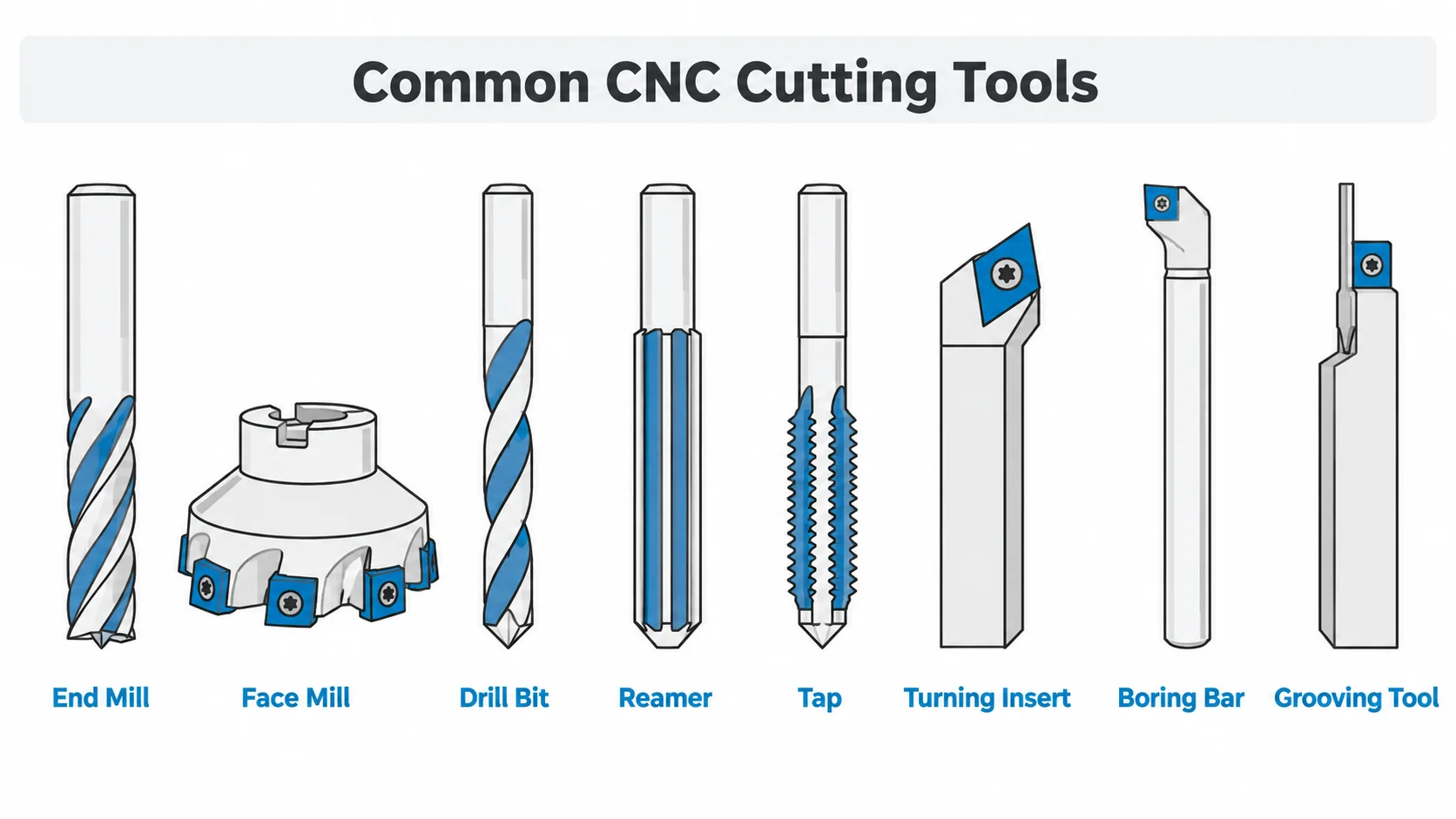
End Mills
End mills are among the most common tools used in CNC milling.
Unlike drill bits, which primarily cut in the axial direction, end mills can remove material from both their sides and ends. This allows them to machine pockets, slots, profiles, shoulders, and complex contours.
Common end mill types include:
Flat end mills for pockets, slots, and flat-bottom features.
Ball nose end mills for curved surfaces, molds, dies, and 3D contour machining.
Corner-radius end mills for combining good strength with smooth internal corners.
The number of flutes also affects performance. Lower flute counts usually provide more chip space, while higher flute counts provide more cutting edges.
A practical starting point:
- 2–3 flutes for aluminum and other soft, gummy materials that need chip room
- 4 flutes as the general-purpose choice for steel, stainless steel, and mixed work
- 5–7 flutes for finishing, high-feed roughing, and rigid setups where chip evacuation is less difficult
Tool selection is usually made together with the CNC milling process plan, because flute count, toolpath, and fixturing all influence the same result.
Face Mills
Face mills are mainly used to machine large flat surfaces.
Instead of using a solid cutting edge along the tool body, many face mills use replaceable carbide inserts positioned around the cutter.
They are commonly used for surface flattening, stock removal, preparing reference surfaces, and machining large metal plates or blocks.
Face milling can often remove material faster than using a smaller end mill across a wide surface, and it tends to produce a better flatness result on large faces because the load is spread over several inserts.
Drill Bits
Drill bits produce round holes in solid material.
Common CNC drills include twist drills, carbide drills, indexable drills, center drills, and specialized deep-hole drills.
Drilling is usually the first operation used to create a hole, but drilling alone may not provide sufficient accuracy for critical bores.
For tighter hole tolerances or better surface finishes, the drilled hole may be followed by reaming or boring.
Hole depth matters as well. As a general rule, a hole deeper than about 4 times the drill diameter needs better chip evacuation and coolant delivery, and depth-to-diameter ratios above 10 usually call for a dedicated deep-hole strategy.
For reference sizes and tap drill diameters, see our drill size chart.
Reamers
A reamer removes a small amount of material from an existing hole to improve diameter accuracy, roundness, and surface finish.
Reaming is usually used after drilling.
It is well suited to precision pin holes, locating holes, bearing bores, and other features where the final hole size is more important than material removal rate.
Because a reamer only removes a small amount of stock — typically 0.1 to 0.5 mm on diameter — the pre-drilled hole must already be relatively close to the final diameter.
A hole that is drilled too large, out of round, or not straight cannot be corrected by reaming.
Taps and Thread Mills
Taps and thread mills are both used to produce internal threads, but they work differently.
A tap cuts the entire thread profile as it rotates into the hole. Tapping is generally efficient for common thread sizes and higher production volumes.
A thread mill uses circular interpolation to machine the thread progressively. One thread mill can sometimes produce several thread diameters using the same pitch.
Thread milling can be useful for larger threads, difficult materials, blind holes, and applications where thread control is especially important. It also produces a smaller chip load, which reduces the risk of tap breakage in expensive or hard-to-replace parts.
Thread dimensions, pitch, and tap drill sizes are listed in our thread size chart.
Turning Tools
CNC turning tools are used on lathes, Swiss machines, and mill-turn machines.
The workpiece rotates while the cutting tool removes material from its outer or inner diameter.
Common turning operations include facing, outside-diameter turning, taper turning, profiling, threading, grooving, and finishing.
Many modern turning tools use replaceable carbide inserts. Insert shape, nose radius, chip breaker, and grade are selected according to material and machining conditions.
Because turning tools are indexed rather than reground, the edge condition and insert grade often matter more than the tool body itself. Details of the process are covered in our CNC turning service page.
Boring Bars
Boring bars enlarge or finish holes that already exist.
They are especially useful when a drilled hole requires better concentricity, diameter control, straightness, or surface quality.
Boring can also machine internal shoulders, tapers, and larger internal diameters that cannot be finished effectively with a reamer.
Boring bars are inherently less rigid than many other tools because they must reach inside the workpiece. Bore depth, bar diameter, and material all influence how much vibration the setup can tolerate.
Grooving and Parting Tools
Grooving tools cut narrow channels on the outer or inner diameter of a turned component.
Typical applications include retaining-ring grooves, O-ring grooves, relief grooves, and sealing features.
Parting tools are similar but are primarily used to cut a completed part away from bar stock.
Tool rigidity and chip control are particularly important because grooving and parting tools are often narrow and exposed to high cutting loads.
Chamfer and Countersink Tools
Chamfer cutters remove sharp edges and create angled transitions between surfaces.
They are commonly used for deburring, edge breaking, assembly preparation, and cosmetic finishing.
Countersink tools produce a conical recess around a hole so that a flat-head screw can sit flush or below the surface.
The required tool angle depends on the fastener standard and drawing specification. Chamfers are often added in the same setup as the parent feature, which keeps the edge concentric with the hole or profile it belongs to.
CNC Cutting Tool Materials
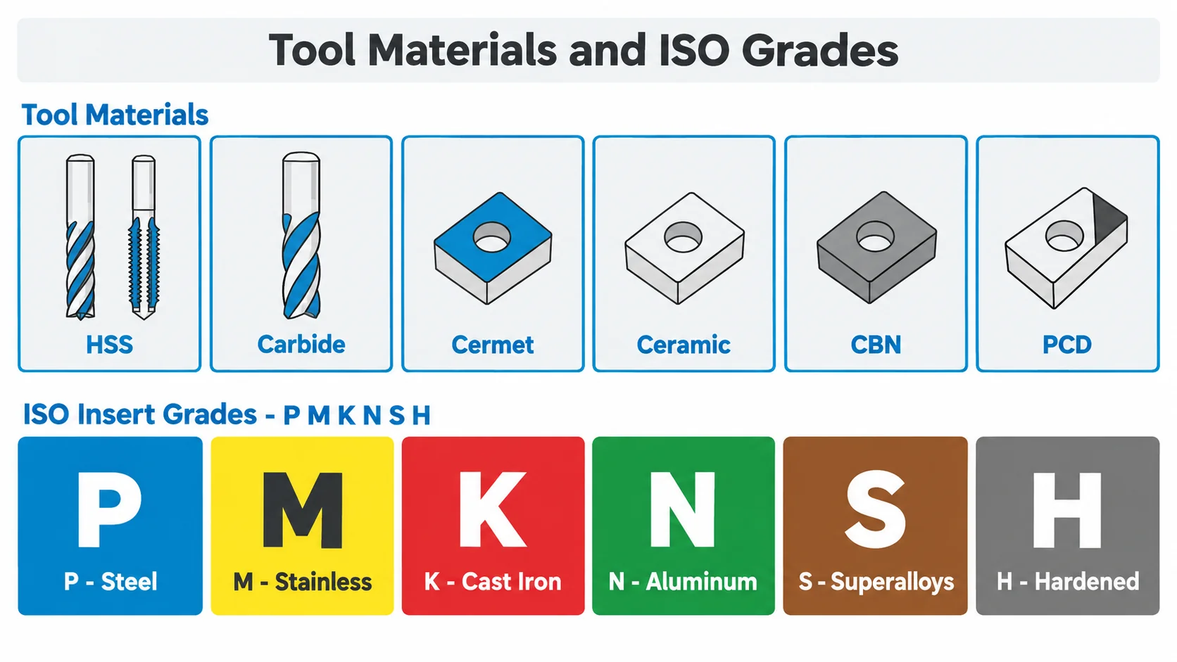
The cutting tool material determines how well a tool resists heat, wear, impact, and cutting forces.
| Tool Material | Wear Resistance | Toughness | Typical Cutting Speed | Common Uses |
|---|---|---|---|---|
| HSS | Medium | High | Low to Medium | General drilling, tapping, low-volume work |
| Carbide | High | Medium | High | Most CNC milling and turning |
| Cermet | High | Medium-Low | High | Steel finishing |
| Ceramic | Very High | Low | Very High | High-speed machining of cast iron and superalloys |
| CBN | Very High | Medium | High | Hardened steels |
| PCD | Extremely High | Low | Very High | Aluminum, copper alloys, composites |
High-Speed Steel
High-speed steel, or HSS, is tougher and less brittle than carbide.
It is commonly used for drills, taps, reamers, and lower-speed machining applications.
HSS tools are usually less expensive than carbide tools and can tolerate interrupted cutting or less rigid setups relatively well.
However, they cannot usually maintain cutting performance at the same speeds and temperatures as carbide. In practice, carbide is often run at two to five times the cutting speed of HSS in the same material, although the exact ratio depends on the grade, coating, and machine rigidity.
Carbide
Carbide is the most widely used cutting tool material in modern CNC machining.
It offers much higher hardness and heat resistance than HSS, allowing higher spindle speeds, feed rates, and production efficiency.
Carbide is commonly used for end mills, drills, turning inserts, boring tools, face-mill inserts, and threading tools.
Its main disadvantage is lower toughness compared with HSS. Poor fixturing, vibration, or impact can cause chipping.
Carbide grades are also not all the same. Fine and submicron grain grades trade some toughness for edge sharpness and wear resistance, which makes them useful for small-diameter tools and finishing operations, while coarser grades are better suited to interrupted cuts and roughing.
Cermet
Cermet tools combine ceramic and metallic materials.
They provide good wear resistance and can generate excellent surface finishes, particularly when finishing steels.
However, cermets are generally less resistant to impact and interrupted cuts than tougher carbide grades.
Ceramic
Ceramic cutting tools maintain hardness at extremely high temperatures.
They can be used for high-speed machining of cast iron, hardened materials, and certain heat-resistant alloys.
Because ceramics are brittle, they generally require stable machining conditions and rigid setups. They also usually run dry or with minimal lubrication, since thermal shock from coolant can crack the edge.
CBN
Cubic boron nitride, or CBN, is commonly used for hardened steels and other very hard ferrous materials.
CBN tools can maintain cutting performance at high temperatures and often provide good tool life in hard turning applications.
They are more expensive than carbide, so they are usually reserved for applications where their performance justifies the higher tool cost — typically hardened parts above roughly 45 HRC, or where grinding would otherwise be required.
PCD and Diamond Tools
Polycrystalline diamond, or PCD, offers extremely high wear resistance and low friction.
It is particularly useful for machining aluminum alloys, copper alloys, composites, graphite, and abrasive non-ferrous materials.
PCD is generally not preferred for ferrous materials at high cutting temperatures because diamond can react with iron.
ISO Insert Grades: P, M, K, N, S, and H
Turning, milling, and grooving inserts are usually classified by ISO application groups. The color coding on the insert box corresponds to these groups, and the letter indicates the workpiece material the grade was designed for.
| ISO Group | Workpiece Material | Color Code | Practical Notes |
|---|---|---|---|
| P | Steel | Blue | Most common group; coated grades dominate |
| M | Stainless steel | Yellow | Needs a sharp, strong edge to avoid work hardening |
| K | Cast iron | Red | Uncoated or thin-coated grades work well |
| N | Aluminum and non-ferrous | Green | Sharp polished edges; PCD often used |
| S | Titanium and superalloys | Brown | Heat management and edge strength are critical |
| H | Hardened steel | Grey | CBN and ceramic grades for hard turning |
Grades are also refined within each group by a number or range, for example a tougher grade for roughing and a harder, more wear-resistant grade for finishing.
Selecting the correct group is often the single largest factor in insert tool life. A grade intended for steel will usually fail quickly in stainless steel or titanium, even if the shape and size are correct.
Common CNC Tool Coatings
Tool coatings can reduce friction, increase surface hardness, improve heat resistance, and extend tool life.
| Coating | Main Advantage | Typical Applications |
|---|---|---|
| TiN | General wear resistance | General machining |
| TiCN | Higher hardness than TiN | Steel and tougher materials |
| TiAlN / AlTiN | Excellent heat resistance | Steel, stainless steel, titanium |
| ZrN | Low friction and anti-adhesion | Aluminum and non-ferrous alloys |
| DLC | Very low friction | Aluminum, copper, plastics |
TiN
Titanium nitride is one of the most familiar tool coatings.
It improves wear resistance and can reduce friction compared with an uncoated tool.
TiN is commonly used as a general-purpose coating.
TiCN
Titanium carbonitride provides greater hardness and wear resistance than conventional TiN.
It can perform well in steels and other materials where abrasion resistance is important.
TiAlN and AlTiN
TiAlN and AlTiN coatings are designed for higher cutting temperatures.
They are widely used for machining steels, stainless steels, and titanium alloys.
These coatings are particularly useful when heat is concentrated at the cutting edge. Aluminum-rich AlTiN variants are often preferred for hardened materials and dry or near-dry machining, while TiAlN is a common choice for stainless steel and general steel work.
ZrN
Zirconium nitride has relatively low friction and helps reduce material adhesion.
It is commonly used when machining aluminum and other non-ferrous materials where built-up edge can become a problem.
DLC
Diamond-like carbon coatings provide very low friction and good resistance to adhesion.
They are often used for non-ferrous metals and engineering plastics.
PVD vs CVD Coating Processes
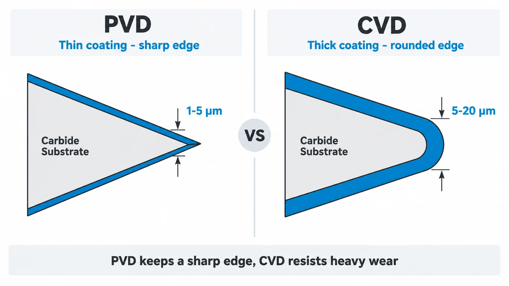
Coating names describe the chemistry; the deposition process describes how the coating is applied. The two most common processes are PVD and CVD, and they behave differently at the cutting edge.
| Factor | PVD | CVD |
|---|---|---|
| Typical thickness | About 1–5 µm | About 5–20 µm |
| Process temperature | Lower | Much higher |
| Edge sharpness | Retains a sharp edge | Edge rounding is more typical |
| Adhesion and wear resistance | Good | Very good for heavy wear |
| Typical use | Sharp tools, drilling, threading, small diameters | Turning and milling inserts in steel and cast iron |
Because PVD keeps the edge sharper, it is often used for taps, drills, small end mills, and high-hardness substrates. CVD is common on indexable inserts and provides excellent resistance to abrasive wear, but the higher process temperature limits the substrate grades it can be applied to.
How Tool Geometry Affects CNC Machining
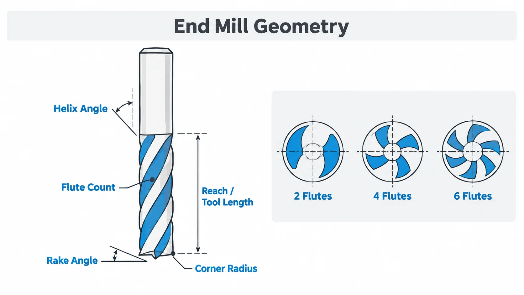
Tool material alone does not determine cutting performance. Tool geometry is equally important.
Flute Count
Flutes are the cutting edges running along an end mill.
Fewer flutes provide larger chip spaces, which can improve chip evacuation when machining materials such as aluminum.
Higher flute counts provide more cutting edges and can increase productivity in materials where chip evacuation is less difficult.
Flute count also affects feed rate, because feed per tooth must be multiplied by the number of teeth.
Helix Angle
The helix angle affects cutting smoothness, chip movement, cutting forces, and tool strength.
Higher helix angles often provide smoother cutting action, while lower helix angles can offer a stronger cutting edge in demanding applications.
Typical ranges:
- 30° — general-purpose milling in steel
- 35–45° — aluminum, finishing, and thin-wall parts where cutting forces should be directed upward
- 50° and above — high-shear finishing where the setup is rigid
- Lower helix or straight flute — harder materials and slotting where edge strength matters
Rake Angle
Rake angle influences how the cutting edge enters the workpiece and how chips flow away from the cutting zone.
Sharp positive rake geometry can reduce cutting forces in softer materials, while stronger edge geometry may be needed for harder materials.
In practice, aluminum and plastics favor a sharp positive rake, stainless steel and titanium favor a stronger edge with modest rake, and hardened or interrupted cuts often need a negative or reinforced geometry.
Tool Diameter
Larger tools usually provide greater stiffness and can remove material faster.
Smaller tools are required for narrow slots, small pockets, and detailed features.
Tool diameter must therefore be matched to the smallest machined feature.
Tool Reach
Long tools can access deep cavities but are more prone to deflection and vibration.
Whenever possible, the shortest tool that can reach the feature should be used to improve rigidity and dimensional stability.
A common rule of thumb is to keep the length-to-diameter ratio of the cutting tool as low as possible, and to reduce cutting parameters as the reach increases.
Corner Radius
Adding a radius to the cutting edge can strengthen the tool and improve tool life.
However, tool radius must match the part geometry and internal-corner requirements.
A radius that is too small concentrates stress at the corner, while a radius that is too large can leave material in internal corners that the drawing does not allow.
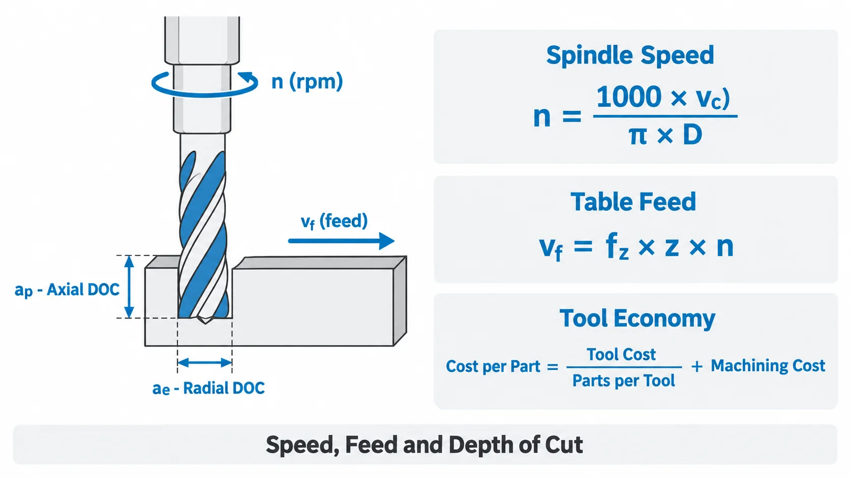
Cutting Parameters: Speed, Feed, and Depth of Cut
Even a correctly selected tool will perform poorly with unsuitable cutting parameters. Three values drive most machining decisions: cutting speed, feed, and depth of cut.
Cutting speed (vc) is the surface speed between the tool and the workpiece, usually expressed in m/min or surface feet per minute. Spindle speed follows from it:
n = (1000 × vc) / (π × D)
where n is spindle speed in rpm and D is tool diameter in mm.
Feed per tooth (fz) is how much material each cutting edge removes per revolution. Table feed is calculated as:
vf = fz × z × n
where z is the number of flutes. This is why flute count matters: at the same feed per tooth, a six-flute cutter can be fed much faster than a two-flute cutter.
Depth of cut is split into axial depth (how deep the tool engages) and radial depth (how wide). Shallow radial engagement with higher axial depth is the basis of high-feed and high-speed strategies, while full-width slotting is the most demanding case for any tool.
The table below shows typical starting ranges for carbide and HSS tools. Values must be adjusted for machine rigidity, tool reach, coolant, coating, and part setup.
| Workpiece Material | Carbide Cutting Speed (m/min) | HSS Cutting Speed (m/min) | Notes |
|---|---|---|---|
| Aluminum alloys | 300–1000 | 60–150 | High speed, large chip room, sharp edge |
| Brass and copper | 200–500 | 50–120 | Watch for material adhesion on copper |
| Carbon and alloy steel | 120–250 | 25–45 | Coated carbide is standard |
| Stainless steel | 80–180 | 15–30 | Avoid dwelling to limit work hardening |
| Titanium alloys | 40–90 | 10–25 | Heat stays at the edge; use generous coolant |
| Cast iron | 100–300 | 20–40 | Dry or minimal coolant is often preferred |
| Plastics (POM, PEEK) | 200–600 | 60–200 | Very sharp edges, control heat and burrs |
Two practical rules reduce most parameter mistakes. First, increase speed before increasing feed when the tool starts to rub, because rubbing generates heat without cutting. Second, reduce radial engagement rather than cutting speed when vibration appears, because vibration damages the edge faster than speed does.
Tool Holders, Runout, and Tool Life
The tool is only as good as the interface that holds it. Tool holders, clamping method, and concentricity all influence how the cutting edge actually behaves in the cut.
Common holder types include:
- ER collet chucks — flexible and economical for a wide range of tool diameters
- Hydraulic holders — excellent concentricity and damping for finishing
- Shrink-fit holders — very low runout and high rigidity, common in high-speed machining
- Side-lock and whistle-notch holders — strong and simple, but with more runout
- Face mill arbors and shell mill holders — for indexable face and shoulder milling
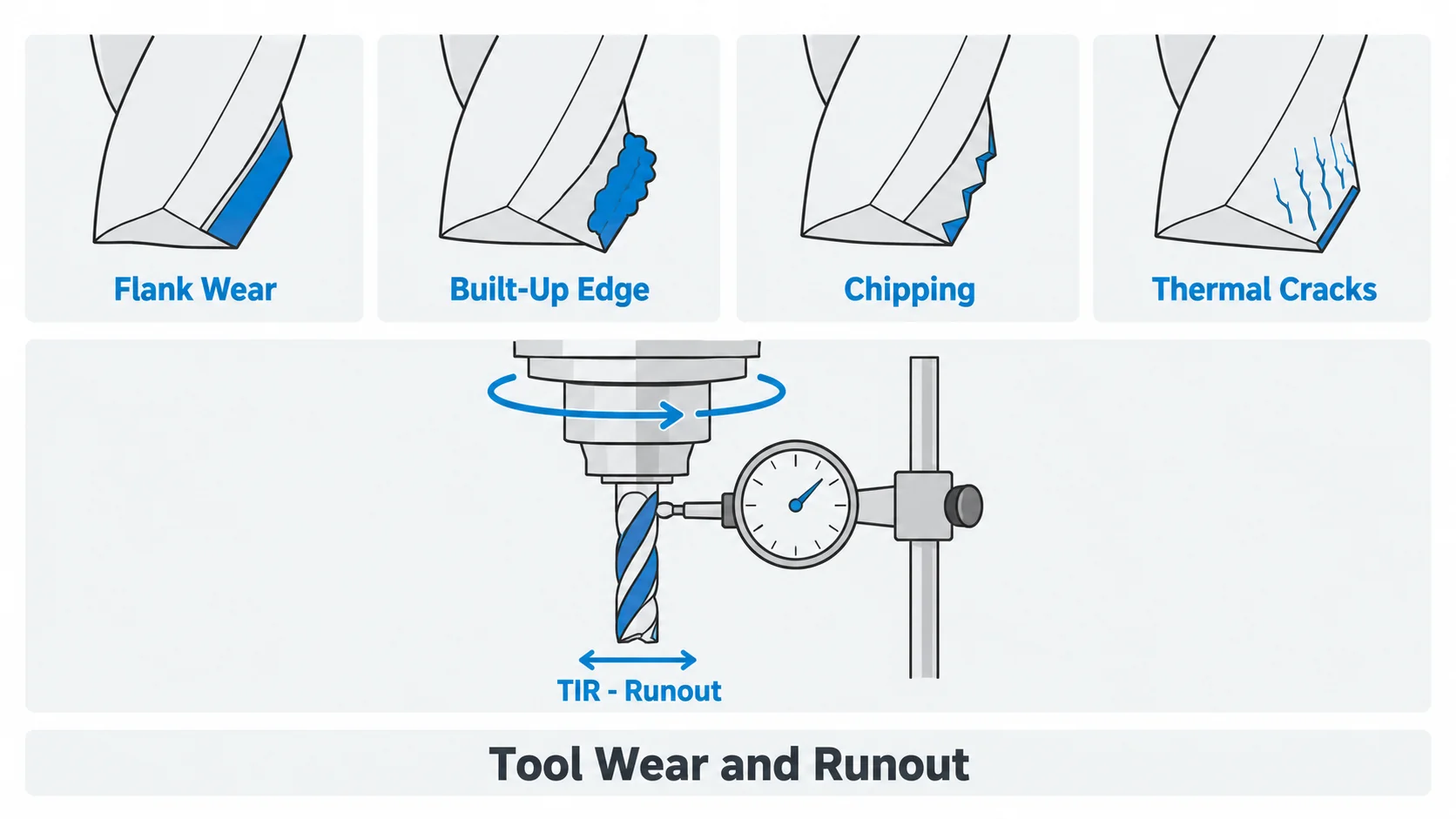
Total indicated runout, or runout, is measured at the cutting edge. High runout means one tooth does most of the cutting, which shortens tool life, worsens surface finish, and can cause chatter. As a working guideline, most precision milling operations aim for runout under about 0.01 mm at the tool, and finishing operations in small diameters aim tighter still.
Tool life itself is not a fixed number. It depends on the material, cutting parameters, coolant, holder condition, and how consistently the tool engages the workpiece. Many shops define tool life by flank wear land, by surface finish degradation, or simply by a fixed number of parts before replacement.
Tool Wear Types and What They Tell You
Reading wear patterns is one of the fastest ways to diagnose a process. The most common wear forms are:
Flank wear — normal abrasive wear on the clearance face. It is the expected wear mechanism and the basis of most tool life criteria.
Crater wear — a depression on the rake face caused by high temperature and diffusion, common when cutting steel at high speed.
Built-up edge — material welded to the edge, which then breaks away and takes tool material with it. It is common in aluminum, copper, and soft steels, and is usually a sign that cutting speed is too low or the edge is not sharp enough.
Chipping and micro-chipping — small fractures along the edge, usually caused by vibration, interrupted cuts, or excessive feed.
Thermal cracking — a network of cracks perpendicular to the edge, typically caused by interrupted cutting with coolant cycling heat in and out of the tool.
Notch wear — localized wear at the depth-of-cut line, common in stainless steel, titanium, and work-hardening materials.
Different patterns point to different corrections: change the grade or coating for wear, change the cutting speed for built-up edge, and change the fixturing, engagement, or feed for chipping.
How to Choose the Right CNC Cutting Tool
The best cutting tool is selected by considering the complete machining process rather than only the tool type.
A practical selection sequence is:
Machining operation → workpiece material → feature geometry → tolerance and surface finish → machine capability → tool material and coating → tool life and cost per part.
For example, machining a deep aluminum pocket may require a sharp carbide end mill with good chip evacuation and sufficient reach.
Machining hardened steel may instead require a coated carbide or CBN tool capable of resisting high cutting temperatures.
For precision production, the lowest-cost tool is not always the most economical choice. A more expensive tool may reduce cycle time, improve consistency, and require fewer tool changes. When comparing options, calculate cost per part rather than cost per tool:
Cost per part = tool cost / parts per tool + machining cost per part
A tool that costs twice as much but machines three times as many parts before replacement usually wins, particularly on parts with significant cycle time.
CNC Tool Selection by Machining Operation
| Machining Feature or Operation | Typical CNC Cutting Tool |
|---|---|
| Large flat surface | Face mill |
| Flat end mill | |
| Slot | End mill or slot cutter |
| 3D contour | Ball nose end mill |
| Hole from solid | Drill |
| Precision hole | Reamer or boring tool |
| Large accurate bore | Boring bar |
| Internal thread | Tap or thread mill |
| External thread | Threading insert or thread mill |
| Chamfer | Chamfer mill |
| Countersink | Countersink cutter |
| OD turning | Turning insert |
| Internal turning | Boring bar |
| Groove | Grooving insert |
| Part cut-off | Parting tool |
The actual selection still depends on part geometry, hole depth, material, tolerance, and machine setup.
CNC Tool Selection by Workpiece Material
Different materials generate different cutting forces, temperatures, chip behavior, and wear mechanisms.
| Workpiece Material | Typical Tool Material | Recommended Tool Characteristics | Common Coating Options |
|---|---|---|---|
| Aluminum | Carbide | Sharp edge, large chip space, polished flute | Uncoated, ZrN, DLC |
| Stainless Steel | Carbide | Strong cutting edge, controlled chip breaker | TiAlN, AlTiN |
| Alloy Steel | Carbide | Strong geometry and heat resistance | TiAlN, AlTiN |
| Titanium | Carbide | Sharp but strong edge, good heat management | TiAlN, AlTiN |
| Brass | Carbide | Sharp polished cutting edge | Uncoated, ZrN |
| Copper | Carbide | Sharp geometry, low-friction surface | Uncoated, DLC |
| POM | Carbide | Very sharp edge and good chip clearance | Uncoated |
| PEEK | Carbide | Sharp edge with controlled heat generation | Uncoated, DLC |
Aluminum
Aluminum is relatively easy to machine but can stick to the cutting edge.
Sharp carbide tools with large flute spaces help evacuate chips and reduce built-up edge.
Uncoated polished tools, ZrN coatings, and DLC coatings are commonly used depending on the operation. Two or three flutes are common for roughing, while higher counts are used for finishing where chip room is less critical. Machining aluminum parts is usually the most forgiving application in a machine shop, which also makes it a good starting point when validating a new process.
Stainless Steel
Stainless steel can generate significant heat and may work-harden if machining conditions are poor.
Carbide tools with strong cutting edges and heat-resistant coatings are commonly used for stainless steel parts.
Good chip control and consistent cutting engagement are also important. Avoid dwelling in the cut, keep the feed high enough to stay under the work-hardened layer, and use plenty of coolant.
Alloy Steel
Alloy steels such as 4140 may vary significantly in machinability depending on hardness and heat treatment.
Carbide tools with wear-resistant coatings are common for production machining.
Harder conditions may require stronger tool grades, reduced cutting speeds, or specialized inserts. Pre-hardened grades are usually machined in the 28–35 HRC range without difficulty, while harder conditions begin to favor CBN or ceramic grades for finishing.
Titanium
Titanium has relatively low thermal conductivity, so heat tends to remain concentrated around the cutting edge.
Rigid workholding, sharp tools, controlled engagement, and suitable coolant strategies are important.
Carbide tools are commonly used for titanium because they provide the strength and temperature resistance required for productive titanium machining. Cutting speeds stay low, feeds stay generous, and the tool should never be allowed to rub.
Brass and Copper
Brass usually machines cleanly and can often achieve excellent surface finishes.
Sharp carbide tools are commonly used for brass parts.
Copper is more prone to smearing and material adhesion, so low-friction, sharp tool geometry is particularly important.
POM and PEEK
Engineering plastics generally require very sharp cutting edges.
Poor tool geometry can create heat, burrs, melting, or dimensional instability.
Tools with polished flutes and good chip clearance are commonly preferred.
For PEEK and other high-performance polymers, cutting heat should be controlled carefully, especially on thin walls and tight-tolerance features. Some shops use compressed air rather than coolant to avoid thermal shock and contamination.
How Cutting Tool Selection Affects Part Quality
Cutting tool selection directly influences the quality and cost of CNC-machined parts.
A tool that is too flexible may deflect and produce dimensional errors. A dull or unsuitable tool may create excessive burrs, poor surface finish, vibration marks, heat, or inconsistent dimensions.
Tool choice also affects cycle time.
A properly selected carbide cutter may allow higher feeds and speeds than an HSS tool, while a suitable coating may extend tool life during stainless steel or titanium machining.
Surface quality is often the first symptom of a tooling problem. Scratches, smearing, or chatter marks usually point to edge condition, runout, or parameter choice rather than the machine itself. For reference values, see our surface roughness chart and our guide to CNC machining tolerances.
For tight-tolerance or complex parts, manufacturers normally evaluate cutting tools together with fixture design, machining sequence, coolant strategy, toolpath, and inspection requirements.
This is particularly important in 5-axis machining, Swiss machining, mill-turn machining, and precision CNC milling, where multiple tools may be required to complete a single component.
Conclusion
CNC cutting tools include end mills, face mills, drills, reamers, taps, thread mills, turning tools, boring bars, grooving tools, and other specialized cutters.
However, selecting the right tool requires more than identifying the machining operation.
The workpiece material, tool material, coating, cutting geometry, feature size, tolerance, surface finish, machine rigidity, and production volume all need to be considered together.
For most CNC machining applications, carbide tools provide a good balance of cutting speed, wear resistance, and productivity. HSS remains useful for certain drilling and threading applications, while ceramic, CBN, and PCD tools are used for more specialized machining conditions.
The most effective tool is ultimately the one that achieves the required part quality, tool life, and production efficiency for the specific application.
At YUANYI Precision Manufacturing, we review part geometry, material, tolerances, and production volume before selecting tooling and machining strategy, so that tool life and part quality stay consistent from prototype runs through series production.
Have a part that is difficult to machine, or a tooling problem you cannot solve? Send us your drawing and requirements for a DFM review and quotation.
Frequently Asked Questions
Carbide end mills and carbide turning inserts are among the most widely used CNC cutting tools because carbide provides high hardness, good wear resistance, and the ability to operate at higher cutting speeds than HSS.
A drill bit is primarily designed to cut axially and create round holes. An end mill can cut both axially and laterally, allowing it to machine slots, pockets, profiles, and complex surfaces.
Sharp carbide tools with good chip clearance are commonly used for aluminum. Uncoated polished carbide, ZrN-coated tools, and DLC-coated tools can help reduce material adhesion and built-up edge. Two or three flutes are typical for roughing, with higher flute counts for finishing.
Carbide tools with strong cutting edges and heat-resistant coatings such as TiAlN or AlTiN are commonly used for stainless steel. Tool geometry, chip control, coolant, and cutting parameters also have a major effect on tool life.
Carbide is generally preferred for modern CNC production because it can operate at higher cutting speeds and offers greater wear resistance. HSS is tougher, less brittle, and often more economical for certain drills, taps, and low-speed applications.
Precision holes are commonly finished using reamers or boring tools. Reaming is effective when only a small amount of material needs to be removed, while boring provides greater control over hole size, alignment, and internal geometry.
PVD coatings are thinner, applied at lower temperature, and preserve a sharp cutting edge, which suits drills, taps, and small end mills. CVD coatings are thicker and more wear resistant but involve higher process temperatures and produce more edge rounding, so they are common on indexable turning and milling inserts.
Two or three flutes give the most chip room and suit aluminum and other soft materials. Four flutes are the general-purpose choice for steel and stainless steel. Five to seven flutes provide more cutting edges for finishing and higher feed rates when chip evacuation is not the limiting factor.
Spindle speed is calculated as n = (1000 × vc) / (π × D), where vc is the recommended surface speed for the material and D is the tool diameter. Table feed is vf = fz × z × n, where fz is feed per tooth and z is the number of flutes. Verify the result against the machine limits and adjust for rigidity.
Watch for rising cutting forces, increasing noise or vibration, worse surface finish, dimensional drift, and visible flank wear or chipping. Many shops replace tools by measured flank wear land or by a fixed number of parts rather than waiting for failure, because a worn tool damages the part before it breaks.



