

Concentricity in GD&T describes how the centers of circular features relate to a common reference axis. Under the older ASME Y14.5-2009 standard, it specifically controlled the derived median points of a feature relative to a datum axis.
However, ASME Y14.5-2018 removed concentricity as a separate GD&T control, favoring more practical controls such as position and runout. ISO 1101:2017 still includes concentricity and coaxiality specifications.
For engineers and machinists, the important question is not simply whether two diameters share an axis. It is which geometric characteristic matters to the part’s function and how that requirement should be machined and inspected.
What Is Concentricity in GD&T?
In everyday engineering language, concentricity means that two circles or cylindrical features share a common center or axis.
In traditional ASME GD&T, however, concentricity had a more specific definition.
It controlled the derived median points of diametrically opposite surface elements relative to a datum axis.
Consider a stepped shaft with two cylindrical sections:
- The larger diameter establishes datum axis A.
- The smaller diameter is the controlled feature.
- The design requires the smaller section to be centered relative to datum A.
For each cross-section of the controlled diameter, pairs of opposite surface points are measured. The midpoint of each pair must fall within the specified cylindrical tolerance zone.
This is different from simply comparing two fitted cylinder axes or checking the outer surface with a dial indicator.
A feature can have surface-form errors while its derived median points remain close to the datum axis. That distinction is one reason traditional concentricity was difficult to inspect.
Concentricity Symbol, Datum, and Tolerance Zone
The traditional concentricity symbol is ◎, represented by two concentric circles.
For a drawing governed by ASME Y14.5-2009, an illustrative feature control frame is:
◎ | ⌀0.02 | A
| Element | Meaning |
|---|---|
| ◎ | Traditional concentricity control |
| ⌀0.02 | Cylindrical tolerance zone with a diameter of 0.02 mm |
| A | Datum axis used as the reference |
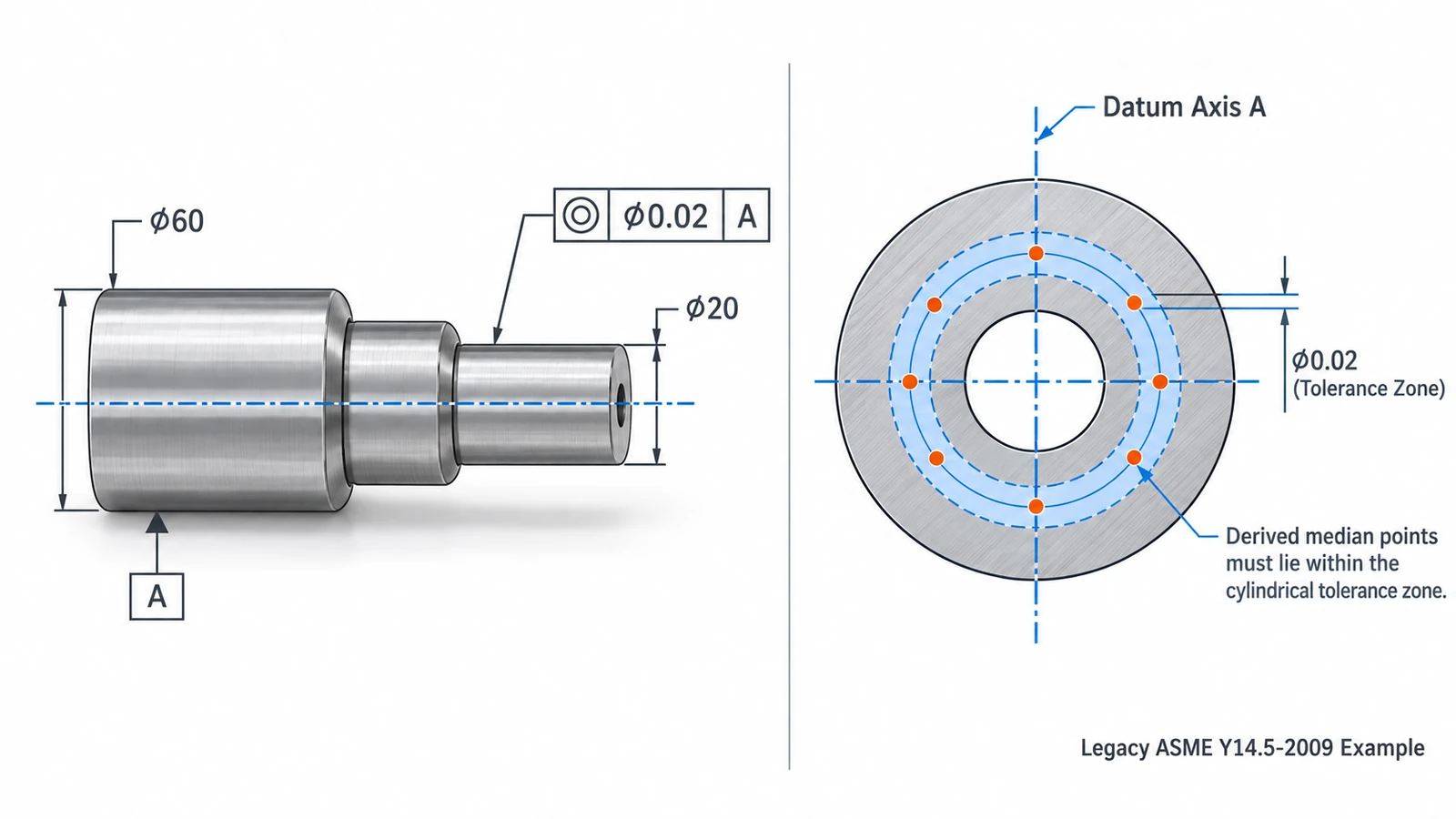
In this example, the derived median points of the controlled cylindrical surface must lie within a cylindrical tolerance zone 0.02 mm in diameter, centered on datum axis A.
The tolerance applies to the evaluated feature along its controlled length, not just one arbitrarily selected cross-section.
Important: This is a legacy ASME drawing example, not a recommended new ASME Y14.5-2018 callout. The applicable drawing standard must be established before interpreting or changing any geometric tolerance.
Is Concentricity Still Used in GD&T?
Yes, but its use depends on the drawing standard.
Concentricity was included in ASME Y14.5-2009 but removed in the 2018 revision. The ISO system continues to provide concentricity and coaxiality controls.
| Standard | Concentricity Status | Practical Meaning |
|---|---|---|
| ASME Y14.5-2009 | Included | Traditional derived median-point control |
| ASME Y14.5-2018 | Removed | Use another appropriate geometric control |
| ISO 1101:2017 | Included | Supports concentricity of points and coaxiality of axes |
Why Did ASME Remove Concentricity?
Traditional concentricity was frequently confused with coaxiality and runout.
Its measurement also required evaluating derived median points rather than directly inspecting the functional surface or a defined feature axis.
In many designs, position or runout provides a more direct and verifiable specification.
The removal does not mean that coaxial alignment is no longer important. It means engineers should communicate the functional requirement using a better-suited geometric control.
What If an Existing Drawing Specifies Concentricity?
First, check the standard and revision referenced in the drawing’s title block.
If the drawing follows ASME Y14.5-2009, the concentricity requirement should be interpreted according to that version.
If the drawing follows ISO 1101, apply the relevant ISO definition rather than assuming it is identical to the older ASME interpretation.
If a drawing references ASME Y14.5-2018 but still contains the deleted symbol, request engineering clarification.
Do not automatically replace a concentricity callout with runout or position using the same tolerance value. These controls evaluate different geometric characteristics, so the replacement may change the design requirement.
Concentricity vs. Coaxiality vs. Runout vs. Position
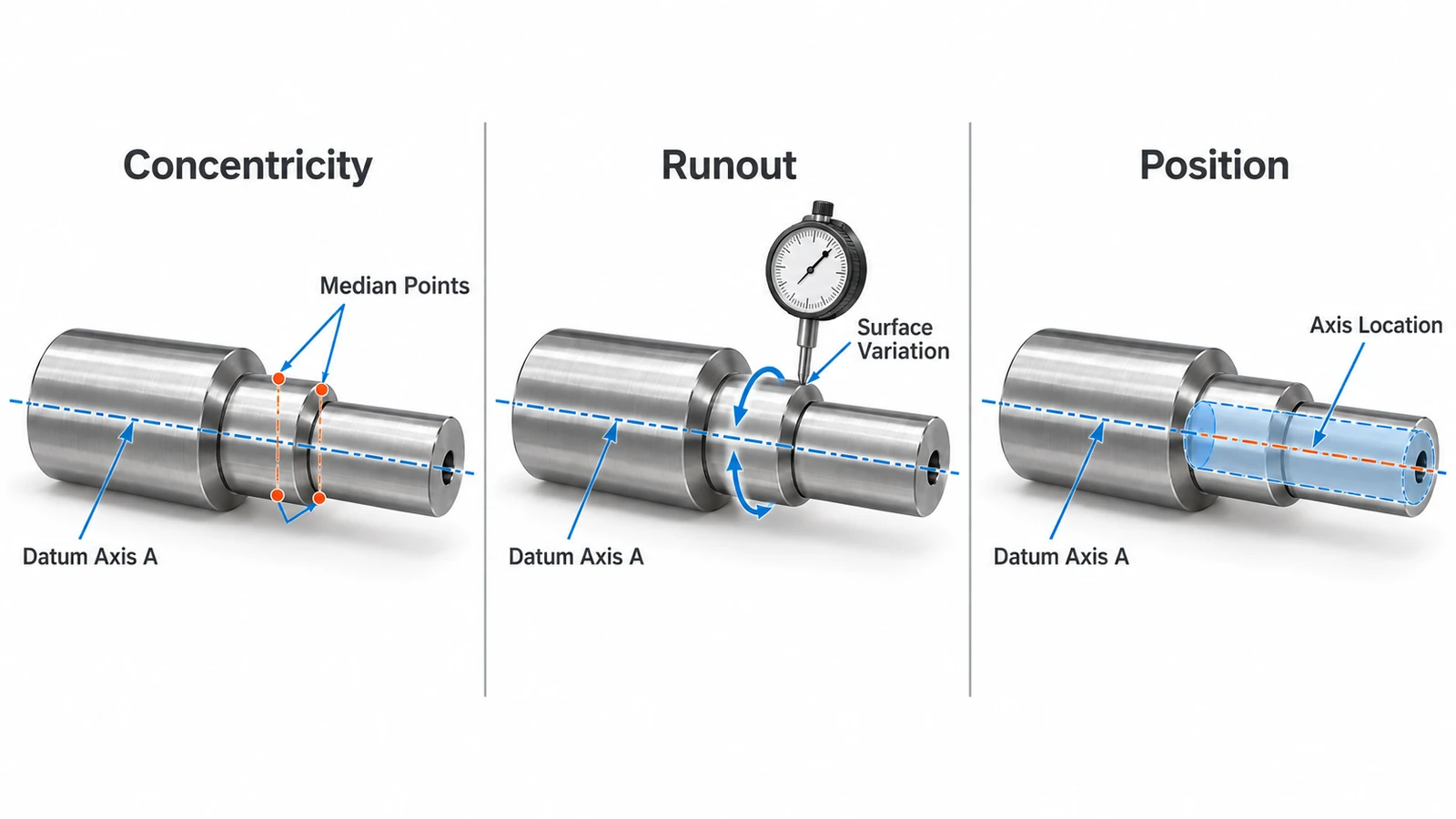
These terms are often used interchangeably in machining discussions, but they do not mean the same thing.
| Control | What It Evaluates | Typical Inspection Approach | Common Application |
|---|---|---|---|
| Legacy ASME concentricity | Derived median points relative to a datum axis | CMM with appropriate evaluation | Older drawings with specific median-point requirements |
| ISO coaxiality | Derived median line or axis relative to a datum axis | CMM or suitable geometric measurement | Alignment of cylindrical features |
| Circular runout | Radial surface variation during one revolution at an evaluated circular section | Dial indicator or CMM | Rotating journals and sealing surfaces |
| Total runout | Composite surface variation over the specified surface during rotation | Indicator traversing the surface or CMM | Precision rotating cylindrical surfaces |
| Position | Location of a feature’s derived axis relative to its specified true position | CMM or appropriate functional gauging | Locating bores, journals, and other features of size |
Concentricity vs. Coaxiality
Both terms relate to central alignment, but the exact requirements depend on the standard.
ISO 1101 distinguishes concentricity specifications for center points from coaxiality specifications for axes or median lines.
Legacy ASME concentricity specifically addresses derived median points taken from opposing surface elements.
Therefore, a statement such as “the two diameters must be concentric” is not a complete manufacturing specification.
A usable drawing needs an applicable standard, a clearly defined datum, and the appropriate tolerance control.
Concentricity vs. Circular Runout
Circular runout measures variation of an actual surface as a part rotates around its datum axis.
For example, a dial indicator contacts a shaft journal while the shaft is rotated through 360 degrees.
The difference between maximum and minimum readings is the total indicator reading, commonly called TIR.
Circular runout is affected by eccentricity and circular form errors. It does not isolate the derived median points used in traditional concentricity evaluation.
Consequently, a runout result of 0.02 mm does not automatically mean the part has a legacy ASME concentricity value of 0.02 mm.
Circular Runout vs. Total Runout
Circular runout evaluates individual circular sections.
Total runout evaluates variation across the entire specified surface as the part rotates and the measurement is taken along its length.
Total runout provides broader control of a cylindrical surface’s relationship to the datum axis, including certain form and alignment errors.
It is useful for long precision journals where consistency across the full bearing or sealing surface matters.
How to Measure Concentricity
The appropriate measurement method depends on the actual GD&T requirement.
A CMM measurement of derived median points, a CMM evaluation of an axis, and a dial indicator runout check are not interchangeable.
1. Measuring Traditional Concentricity with a CMM
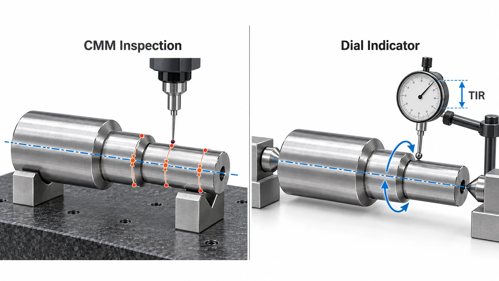
For a legacy ASME concentricity requirement, a coordinate measuring machine (CMM) can collect the necessary surface data.
A typical inspection procedure includes:
- Establish the datum axis using the specified datum feature and an appropriate alignment method.
- Measure multiple cross-sections of the controlled cylindrical surface.
- Collect pairs of surface points located diametrically opposite each other.
- Calculate the midpoint of each opposing pair.
- Evaluate the derived median points against the specified cylindrical tolerance zone.
For example, under a 0.02 mm concentricity tolerance, the evaluated median points must remain within the required 0.02 mm diameter tolerance zone centered on datum A.
The measurement strategy must adequately sample the feature. CMM software should be configured to evaluate the requirement defined by the applicable standard.
Simply comparing the centers of two least-squares fitted circles is not necessarily equivalent to a traditional concentricity evaluation.
2. Measuring Circular Runout with a Dial Indicator
A dial indicator is often a practical choice when the drawing specifies circular runout.
For a stepped shaft:
- Establish a rotation axis corresponding to the specified datum.
- Support the part with a suitable fixture, such as precision centers or another datum-representative setup.
- Position the indicator against the controlled cylindrical surface.
- Rotate the part through one complete revolution.
- Record the maximum and minimum readings.
- Compare their difference with the specified circular runout tolerance.
TIR = Maximum indicator reading − Minimum indicator reading
For example:
- Maximum reading: +0.012 mm
- Minimum reading: −0.008 mm
- TIR: 0.020 mm
The measured circular runout at that section is 0.020 mm.
The result is meaningful only if the fixture, datum simulation, indicator alignment, and measurement setup are suitable for the drawing requirement.
3. Why TIR Cannot Directly Replace Concentricity
An indicator records surface movement, including effects from surface form and eccentricity.
Traditional concentricity evaluates derived median points.
For this reason, dividing TIR by two is not a generally valid method of obtaining a concentricity result.
Even if a simplified eccentric-circle model suggests a mathematical relationship, real machined surfaces may contain ovality, lobing, taper, and other deviations.
Always inspect the characteristic actually specified on the engineering drawing.
How to Choose the Right GD&T Control
The best control depends on what the feature must accomplish in the final assembly.
| Design Requirement | Control to Consider | Why |
|---|---|---|
| Locate a bore axis relative to a datum | Position | Defines permissible axis location |
| Limit radial variation of a rotating journal at a section | Circular runout | Directly evaluates rotational surface variation |
| Control variation across a full cylindrical bearing surface | Total runout | Covers the entire specified surface |
| Specify an axis relationship under ISO rules | Coaxiality or another applicable ISO control | Communicates axis alignment under the ISO framework |
| Interpret a legacy median-point requirement | Legacy concentricity | Preserves the original drawing requirement |
Example: A Shaft with Two Bearing Journals
Consider a steel stepped shaft with two bearing journals.
The first journal establishes datum A. The second must maintain accurate rotational alignment to avoid excessive vibration and bearing loading.
If the functional concern is the radial movement of the second journal’s surface during rotation, circular runout may be an appropriate control.
If the entire length of that journal must maintain a consistent relationship to the datum axis, total runout may be more suitable.
If the requirement is primarily to locate the derived axis of a feature, position may be more appropriate.
The correct choice depends on the assembly’s function. These controls should not be substituted solely because one is easier to inspect.
How to Improve Concentricity in CNC Machining
Good axis alignment starts with the machining process, not just final inspection.
In precision CNC machining, workholding, machine condition, tool forces, and operation sequencing all affect the relationship between cylindrical features.
Machine Critical Diameters in One Setup
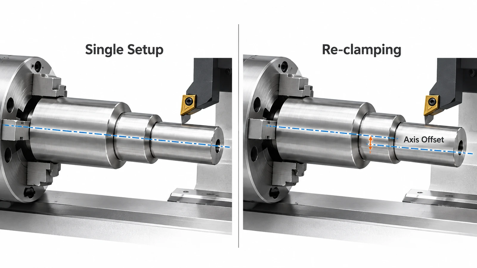
Whenever practical, turn related shaft diameters in the same setup.
A single setup allows critical journals to be generated relative to a consistent spindle and workholding arrangement, reducing errors introduced by repositioning.
However, one-setup machining does not automatically guarantee acceptable runout.
Tool deflection, spindle errors, thermal effects, and workpiece distortion can still affect the result.
Control Re-Clamping and Workholding Errors
Re-clamping is a common source of axis misalignment, particularly on parts requiring machining from both ends.
Possible improvements include:
- Using properly aligned soft jaws or collets
- Locating the workpiece on a controlled reference diameter
- Supporting long shafts with centers or suitable supports
- Reducing unnecessary setup changes
- Inspecting runout after critical re-clamping operations
For thin-walled parts, excessive clamping force can distort the workpiece and create dimensional errors after release.
Reduce Tool Deflection and Thermal Distortion
Long, slender shafts may deflect under cutting forces.
Similarly, unstable cutting conditions, excessive tool overhang, and thermal expansion can create taper or geometric errors.
Appropriate cutting parameters, tool support, workpiece support, and finishing allowances help improve consistency.
Where tolerances exceed the practical capability of conventional turning, cylindrical grinding or another suitable finishing method may be needed.
Inspect Functional Datums
A part can appear accurate when measured using one setup but fail when inspected relative to the drawing’s required datum.
Inspection fixtures must reproduce the intended datum relationship as closely as required by the specification.
For parts with multiple bearing seats, checking the relationship between those seats is often more important than measuring each diameter independently.
Precision CNC turning services are commonly used to manufacture shafts, journals, sleeves, and stepped cylindrical components.
For housings with multiple aligned bores, CNC milling services and precision boring operations help control the required bore relationships.
Common Concentricity Problems in Machined Parts
When a shaft or housing fails its specified geometric tolerance, the first step is to identify which feature, datum, and measurement result are involved.
| Problem | Possible Cause | Recommended Action |
|---|---|---|
| Excessive journal runout | Re-clamping or locating error | Verify datum setup and workholding |
| Misaligned stepped diameters | Multiple setups or tool deflection | Review machining sequence and support |
| Bore-to-OD misalignment | Incorrect locating surface or boring setup | Improve datum-based locating |
| Variation after unclamping | Workpiece distortion | Reduce clamping forces and revise workholding |
| Inconsistent inspection results | Different datum simulation or inspection strategies | Standardize measurement procedure |
| Tolerance failure after heat treatment | Thermal distortion and residual stress | Evaluate finishing after heat treatment |
Avoid correcting a process solely from one indicator reading.
Confirm that the correct GD&T characteristic was measured and that the inspection system is capable of resolving the specified tolerance.
Conclusion
Concentricity is an important concept in precision engineering, but its GD&T meaning depends on the drawing standard.
Traditional ASME concentricity evaluates derived median points, while runout measures actual surface variation and position controls feature location. Selecting the appropriate characteristic makes engineering drawings easier to manufacture, inspect, and verify.
For CNC-machined shafts, bearing journals, and precision housings, reliable geometric accuracy depends on sound datum selection, workholding, machining sequences, and inspection methods.
Need precision-machined components with controlled geometric tolerances? YuanYi Precision Manufacturing provides CNC turning and milling for custom mechanical parts. Contact us with your drawings and tolerance requirements for a manufacturing review.
Frequently Asked Questions
Traditional concentricity controls derived median points relative to a datum axis. Runout measures variation of the actual surface during rotation. They are different geometric controls and their measurement values are not directly interchangeable.
Under a legacy ASME concentricity specification with a diameter symbol, the evaluated derived median points must remain within a cylindrical tolerance zone 0.02 mm in diameter, centered on the specified datum axis.
The exact interpretation depends on the drawing standard and feature control frame.
A dial indicator can measure runout, but it does not directly evaluate the derived median points required for traditional ASME concentricity.
For a legacy concentricity callout, a suitable coordinate measurement and evaluation method is normally needed.
Concentricity was included in ASME Y14.5-2009 but removed in ASME Y14.5-2018. Existing drawings must be interpreted according to their specified standards, and ISO drawings may still contain related concentricity or coaxiality controls.
Machine critical diameters in one setup where possible, use stable datum-based workholding, minimize re-clamping errors, and control tool deflection.
The finished part must still be inspected against the actual geometric tolerance specified on its drawing.



