

Dowel pin hole tolerance determines whether a locating pin fits tightly, slides freely, or requires force during assembly. The correct hole size depends on the pin’s actual diameter tolerance, the required fit, the component material, and the assembly function.
For example, a Ø10 mm H7 hole measures 10.000–10.015 mm, while a Ø10 mm m6 dowel pin measures 10.006–10.015 mm. This combination can produce either slight clearance or interference, depending on the actual manufactured dimensions.
This guide provides metric dowel pin tolerance charts, press-fit and slip-fit comparisons, calculation examples, and practical CNC machining recommendations.
Dowel Pin Hole Size and Tolerance Chart
Hardened cylindrical dowel pins commonly follow ISO 8734, while the dimensional tolerance designations for mating holes and pins are defined through the ISO 286 system.
Many hardened ISO 8734 dowel pins use an m6 diameter tolerance. H7 is a commonly specified mating-hole tolerance, but it does not automatically guarantee a press fit.
The following chart shows common nominal sizes and their corresponding H7 hole and m6 pin limits.
| Nominal Diameter | H7 Hole Limits (mm) | m6 Pin Limits (mm) |
|---|---|---|
| Ø4 | 4.000–4.012 | 4.004–4.012 |
| Ø5 | 5.000–5.012 | 5.004–5.012 |
| Ø6 | 6.000–6.012 | 6.004–6.012 |
| Ø8 | 8.000–8.015 | 8.006–8.015 |
| Ø10 | 10.000–10.015 | 10.006–10.015 |
| Ø12 | 12.000–12.018 | 12.007–12.018 |
| Ø16 | 16.000–16.018 | 16.007–16.018 |
| Ø20 | 20.000–20.021 | 20.008–20.021 |
Reference: ISO 286 tolerance limits for H7 holes and m6 pins, commonly used with ISO 8734 hardened dowel pins. These are dimensional reference values, not universal recommendations for every dowel pin assembly.
How to Read the Chart
Consider a Ø6 mm locating pin.
The H7 hole may measure between 6.000 and 6.012 mm, while the m6 pin may measure between 6.004 and 6.012 mm.
Because these ranges overlap, the pin may be slightly larger or smaller than the mating hole.
The actual fit can therefore vary between interference and clearance.
For a guaranteed clearance or guaranteed interference, the designer must select non-overlapping dimensional limits with sufficient allowance for the complete assembly.
What Is a Dowel Pin Hole?
A dowel pin hole is a precision-machined hole used to position or align components with a cylindrical locating pin.
Unlike an ordinary bolt clearance hole, a dowel pin hole often requires tightly controlled diameter, location, and geometry.
Dowel pins are commonly used in:
- CNC machining fixtures and tooling plates.
- Precision mechanical housings.
- Robotic and automation assemblies.
- Mold and die alignment systems.
- Removable machine components requiring repeatable positioning.
In a typical two-part assembly, one end of the dowel pin may be retained in a base plate, while the opposite end enters a mating hole in a removable component.
The retained end prevents the pin from moving during normal assembly, while the mating end allows the second component to be positioned.
The required fit on each side does not have to be identical.
Press Fit vs Slip Fit vs Transition Fit
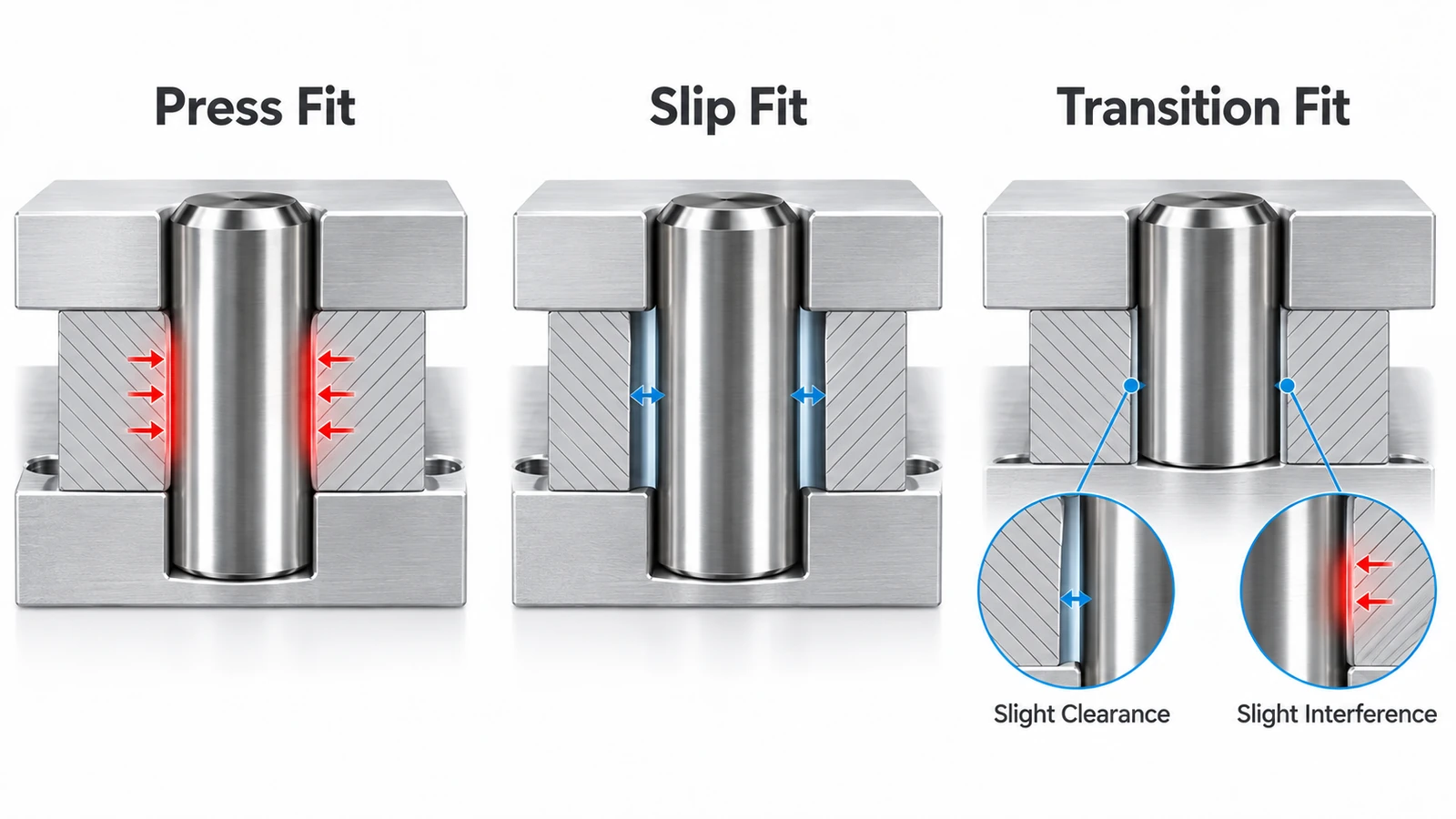
The main difference between these fit types is whether clearance or interference exists between the dowel pin and its hole.
| Fit Type | Dimensional Relationship | Typical Function |
|---|---|---|
| Press Fit | Pin is always larger than the hole | Retaining the pin in a component |
| Slip Fit | Hole is always larger than the pin | Allowing easy insertion and removal |
| Transition Fit | Possible clearance or interference | Controlled location with variable assembly force |
Press Fit
A press fit, also called an interference fit, occurs when the minimum pin diameter is greater than the maximum hole diameter.
The pin is usually installed using controlled force or another approved assembly method.
Press fits are commonly used to retain a locating pin in a permanent or semi-permanent base component.
However, too much interference can deform the hole, damage the pin, or create excessive stress in the surrounding material.
Press-fit requirements must account for material strength, engagement length, edge distance, and assembly conditions.
Slip Fit
A slip fit occurs when the minimum hole diameter is greater than the maximum pin diameter.
This allows the dowel pin to enter without intentional interference.
Slip fits are useful for removable covers, fixtures, and assemblies that require periodic maintenance.
The amount of clearance should be controlled carefully. Excessive clearance can reduce the locating accuracy of the assembly.
Transition Fit
A transition fit has overlapping pin and hole tolerance zones.
Depending on the actual dimensions, the assembled parts may have a small clearance or a small interference.
H7/m6 is a common example of a transition fit.
Although this combination is sometimes described informally as a light press or locating fit, it does not guarantee interference in every assembly.
How to Calculate Dowel Pin Clearance and Interference
The correct way to evaluate a dowel pin fit is to compare the maximum and minimum permitted dimensions.
Use the following equations:
Maximum clearance = Maximum hole diameter − Minimum pin diameter
Minimum clearance = Minimum hole diameter − Maximum pin diameter
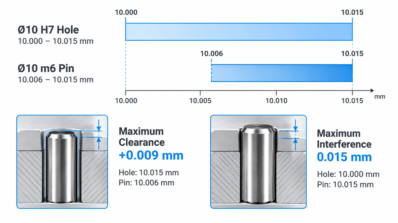
A negative clearance value indicates interference.
Example: Ø10 H7 Hole With Ø10 m6 Pin
Assume the following dimensional limits:
| Component | Minimum Diameter | Maximum Diameter |
|---|---|---|
| H7 hole | 10.000 mm | 10.015 mm |
| m6 pin | 10.006 mm | 10.015 mm |
Maximum clearance:
10.015 − 10.006 = +0.009 mm
Minimum clearance:
10.000 − 10.015 = −0.015 mm
The possible assembled fit therefore ranges from:
0.015 mm interference to 0.009 mm clearance.
This is why H7/m6 is classified as a transition fit.
Two assemblies using components manufactured within exactly the same tolerance specifications may have different insertion forces.
Example: Specifying a Removable Slip Fit
Suppose a Ø10 m6 pin has a maximum diameter of 10.015 mm.
If a designer specifies a custom hole range of 10.025–10.035 mm, the minimum diametral clearance would be:
10.025 − 10.015 = 0.010 mm
The maximum diametral clearance would be:
10.035 − 10.006 = 0.029 mm
This example guarantees positive dimensional clearance across those limits.
However, it is an illustrative custom hole specification, not a universal recommended dowel pin hole tolerance.
The final clearance must be selected according to the required positioning accuracy, material behavior, thermal conditions, and assembly needs.
How to Machine Accurate Dowel Pin Holes
Precision dowel pin holes are commonly manufactured using drilling followed by reaming or precision boring.
The correct process depends on the required diameter, hole position, material, and production volume.
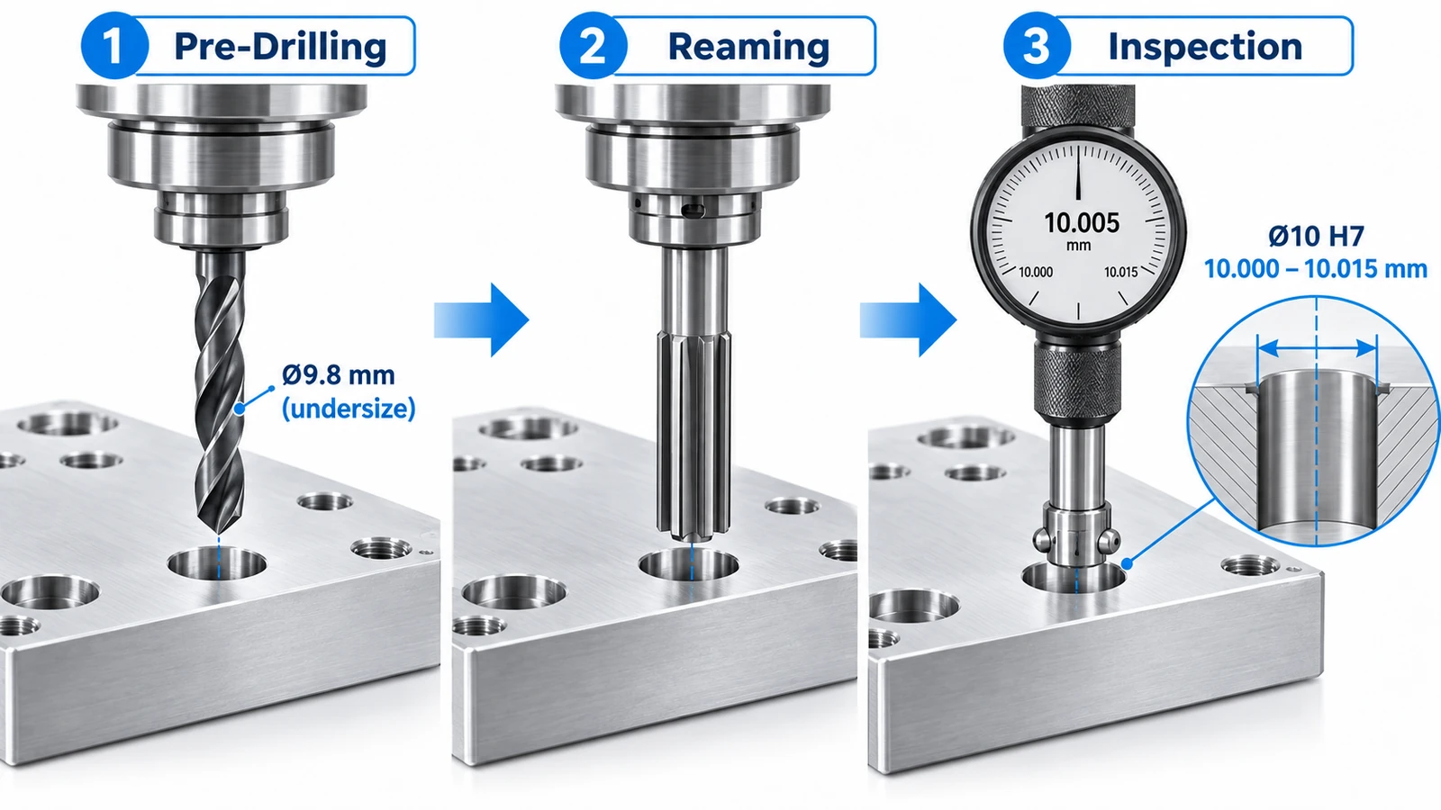
1. Pre-Drilling
The first operation produces a hole slightly smaller than the finished diameter.
The required stock allowance depends on the reamer diameter, material, tool geometry, and manufacturer’s recommendations.
Too much remaining stock can overload the reamer, while insufficient stock may cause rubbing and inconsistent results.
2. Reaming
Reaming uses a multi-edge cutting tool to finish the hole diameter and improve the internal surface.
For example, an accurately positioned pre-drilled hole can be finished to Ø10 H7 using a suitable reamer and controlled machining parameters.
Reaming is often efficient for producing repeated standard-size dowel pin holes.
However, reamers tend to follow the existing hole, so they are not reliable tools for correcting significant positional errors.
3. Precision Boring
Boring provides greater control over the finished hole position and diameter.
It may be preferred when the pre-drilled hole is incorrectly located or when the required finished diameter is nonstandard.
Boring can also be followed by reaming when the application benefits from both operations.
4. Hole Inspection
For precision locating holes, dimensional inspection should verify the functional requirements of the drawing.
Depending on the application, this may include:
- Hole diameter and size limits.
- Position relative to specified datums.
- Roundness or cylindricity where required.
- Hole depth and edge condition.
- Surface finish when functionally important.
A correctly sized hole can still fail if its position is inaccurate.
Dowel Pin Hole Position and Alignment
Dowel pins are commonly used to align components, but the position of each dowel pin hole must be controlled carefully.
Consider two CNC-machined aluminum plates connected by two locating pins.
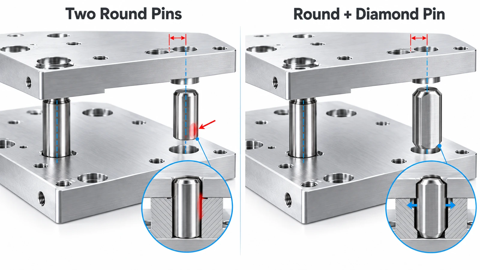
Even if both holes satisfy their H7 diameter limits, assembly may be difficult when the distance between their centers differs between the mating components.
Small position errors can combine with limited clearance to create interference.
Why Two Round Dowel Pins Can Cause Binding
Two closely fitted round dowel pins constrain the relative movement of mating components.
If the hole spacing or alignment differs between the components, the second pin may not enter freely.
This can lead to assembly force, local deformation, or damage to the locating holes.
Depending on the design requirements, possible solutions include:
- Tightening the relevant positional tolerances.
- Machining mating hole patterns in a controlled setup.
- Providing appropriate clearance in a removable mating plate.
- Using one round locating pin and one diamond or relieved locating pin.
A round-and-diamond locating arrangement can constrain the required degrees of freedom while allowing limited variation along a selected direction.
The design must still ensure correct pin orientation and adequate locating accuracy.
Common Dowel Pin Design and Assembly Mistakes
Several common errors can make an otherwise simple dowel pin assembly difficult to manufacture or maintain.
| Design Mistake | Possible Problem | Recommended Approach |
|---|---|---|
| Assuming H7/m6 always gives a press fit | Unexpected clearance | Calculate both dimensional extremes |
| Excessive interference | Hole distortion or material damage | Check the complete fit and material |
| Too much slip-fit clearance | Reduced repeatability | Specify function-based limits |
| Poor hole positioning | Pins cannot align | Apply suitable positional tolerances |
| Two tightly fitted round pins without allowance | Assembly binding | Review round-and-diamond locating |
| Burrs at the hole entrance | Difficult pin installation | Specify controlled edge breaking |
| Inadequate hole depth | Pin bottoms out | Allow suitable depth clearance |
| No removal provision | Difficult maintenance | Consider extraction access or removable pins |
Material Considerations
A press fit in aluminum does not behave exactly like the same dimensional fit in steel.
The materials have different elastic properties, strengths, and thermal expansion characteristics.
For plastic components, creep and environmental conditions may also affect long-term retention.
Therefore, fit calculations based only on nominal dimensions are not sufficient to guarantee retention force or assembly performance.
Critical designs may require engineering analysis and a physical assembly test.
Conclusion
Dowel pin hole tolerance should be selected according to the actual pin dimensions and the intended assembly function.
Press fits provide interference for retention, slip fits provide clearance for removable assembly, and transition fits may produce either result.
For example, a Ø10 H7 hole paired with a Ø10 m6 pin can produce up to 0.015 mm interference or 0.009 mm clearance. This demonstrates why tolerance calculations are essential before specifying a fit.
Accurate CNC machining must also control hole position, geometry, and surface condition to ensure the complete assembly functions correctly.
Need precision CNC-machined locating holes, fixture plates, or mechanical components?
YUANYI provides CNC milling, precision boring, and machining services for custom metal and engineering plastic parts. Send us your CAD files or engineering drawings for a quotation and manufacturability review.
Frequently Asked Questions
Not necessarily. H7 defines a hole tolerance zone. Whether the joint is a press fit, slip fit, or transition fit depends on the dowel pin’s tolerance and actual size limits.
A Ø10 mm m6 dowel pin has a diameter range of 10.006–10.015 mm under the ISO 286 m6 tolerance designation. Other pin standards and tolerance classes may have different limits.
Yes. A dowel pin can be installed in a blind hole, but the hole must provide adequate depth and account for trapped air or fluid, pin-end geometry, and future removal requirements.
Reaming is a common and effective finishing method for precision dowel pin holes. However, boring or other machining methods may be needed when hole position, geometry, or nonstandard diameter requirements are more demanding.
Lubrication requirements depend on the fit, materials, pin coating, and assembly instructions. A lubricant may reduce installation friction, but it should not be added automatically where retention methods or operating conditions prohibit it.



