

Keyway cutting is a machining process used to create a slot in a shaft or hub so a mechanical key can connect two rotating components and transmit torque. Common methods include CNC milling, broaching, keyseating, shaping, and wire EDM. The best method depends on whether the keyway is internal or external, the material, required tolerances, and production quantity.
This guide explains the major keyway cutting methods, how to machine an external shaft keyway, and how to choose suitable dimensions and tolerances.
What Is Keyway Cutting?
A keyway is a machined slot designed to accommodate a mechanical key. Together, the key and mating slots help prevent relative rotation between a shaft and a mounted component, such as a gear, pulley, or coupling.
In a conventional parallel-key connection, three elements work together:
- Key: The separate rectangular metal component that transmits torque.
- Shaft keyseat: The slot machined into the outside diameter of the shaft.
- Hub keyway: The corresponding slot machined into the internal bore of the mating component.
Although keyseat is the more precise term for the slot in a shaft, keyway is commonly used for both features in manufacturing discussions.
Keyways are widely used in industrial machinery, motors, gearboxes, power transmission systems, and automation equipment.
The machining process must control not only the slot width and depth but also its position relative to the shaft or bore axis.
Internal vs External Keyway Cutting
The first step in selecting a keyway cutting method is identifying where the slot must be machined.
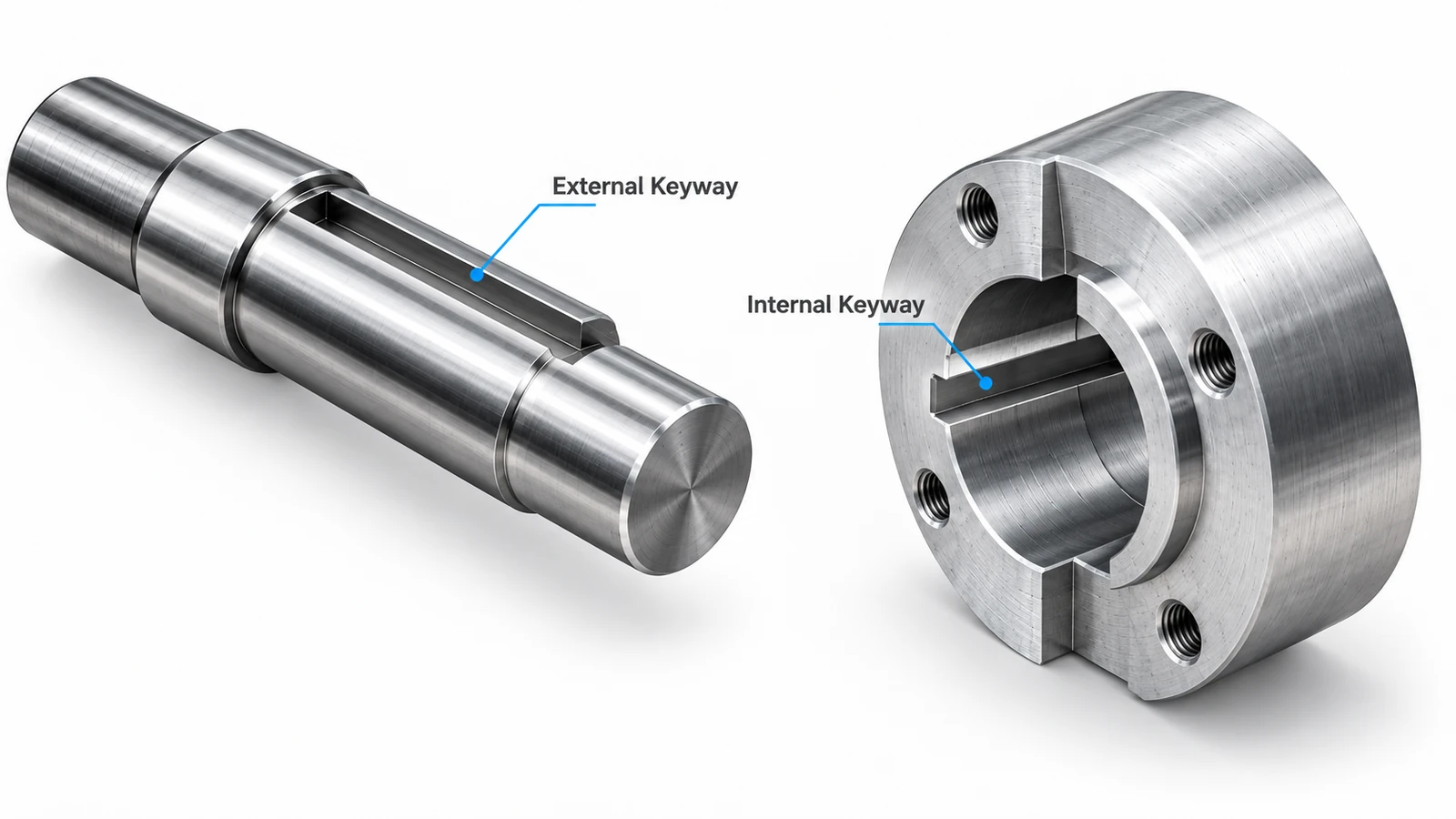
External Keyway Cutting
An external keyway, or shaft keyseat, is machined into the outer surface of a cylindrical shaft.
It is commonly produced using CNC milling, a keyseat cutter, or a suitable slotting operation.
External keyways are relatively accessible because the cutting tool can approach the shaft directly.
Typical applications include:
- Motor shafts
- Gearbox shafts
- Drive shafts
- Pump shafts
- Mechanical transmission components
CNC milling is particularly suitable for prototypes, custom shaft designs, and small-batch production.
Internal Keyway Cutting
An internal keyway is cut into the bore of a hub, gear, pulley, or coupling.
Internal keyways present additional challenges because the cutting tool must operate inside a limited space.
Common methods include broaching, keyseating, slotting, and specialized milling.
The bore configuration is especially important:
Through-hole keyway: The cutting tool can potentially pass through the entire bore, making conventional broaching a practical option.
Blind-hole keyway: The bore terminates inside the component, limiting tool travel and chip evacuation. Specialized keyseating or slotting equipment may be needed, depending on the available clearance.
Wire EDM may also be considered for suitable conductive materials and accessible geometries, but conventional wire EDM requires a continuous wire path and cannot automatically produce a closed-bottom blind keyway.
Therefore, internal and external keyways should not be treated as identical machining operations.
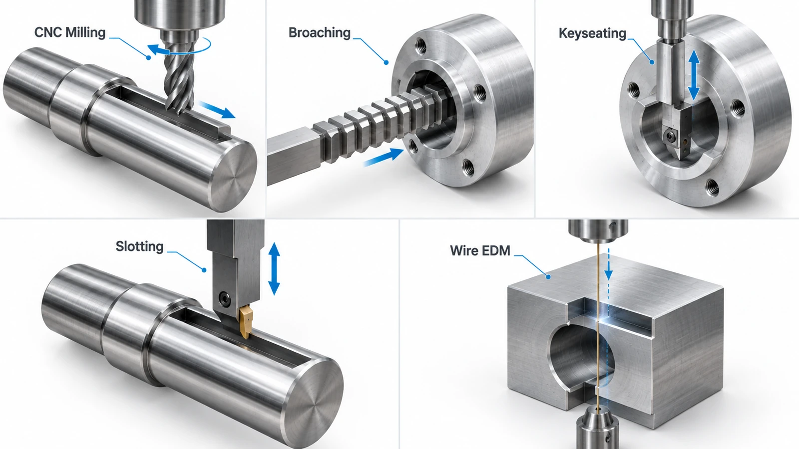
5 Common Keyway Cutting Methods
Different keyway machining methods offer different advantages in accessibility, cycle time, tooling requirements, and manufacturing cost.
1. CNC Keyway Milling
Keyway milling uses a rotating cutter to remove material from a shaft or another accessible surface.
Common cutting tools include:
- Solid carbide end mills
- High-speed steel end mills
- Keyseat cutters
- Woodruff keyseat cutters for suitable semicircular keyseat geometries
For straight shaft keyseats, the cutter follows a programmed toolpath along the required slot length.
Multiple passes may be used to achieve the required depth while maintaining tool stability.
Advantages:
- Flexible for different shaft sizes and slot dimensions
- Suitable for prototypes and low-volume production
- Can be integrated with other CNC milling operations
- Does not always require dedicated keyway machinery
Limitations:
- Cutter deflection can affect slot width and straightness
- Deep, narrow slots may require multiple passes
- Conventional end milling is generally unsuitable for enclosed internal keyways without special tooling or access
For custom shaft components, CNC milling is often a practical starting point.
2. Keyway Broaching
Broaching uses a multi-tooth cutting tool to progressively remove material as it passes through the workpiece.
For internal keyways, a broach is often guided through a prepared bore using a suitable bushing or fixture.
Broaching is particularly effective when producing standardized internal keyways in through-holes.
Advantages:
- Fast cutting once the process is established
- Repeatable slot geometry
- Suitable for medium- and high-volume production
- Efficient for standard keyway sizes
Limitations:
- Requires appropriate broach tooling
- Conventional broaching usually requires an unobstructed tool exit
- Custom tooling may be costly for small batches
- Difficult materials or nonstandard geometries can reduce feasibility
For a detailed explanation of the process, see our guide to broaching machining.
3. Keyseating
Keyseating uses a reciprocating cutting tool to remove material from an internal keyway in successive strokes.
Unlike a conventional through-broach, a keyseating tool can be suitable for certain blind or stepped bores when sufficient cutting travel and relief space are available.
This makes keyseating useful for larger hubs, specialized components, and some nonstandard internal keyways.
Advantages:
- Suitable for many internal keyway geometries
- Can accommodate large bore diameters
- Does not necessarily require a dedicated broach for each slot profile
Limitations:
- Requires suitable equipment and fixtures
- Machining access and stroke clearance must be verified
- Tool deflection and chip removal require attention
4. Shaping and Slotting
Shaping and slotting create keyways using a single-point cutting tool that moves back and forth.
In general, shaping is associated with linear cutting motion, while vertical slotting machines are often used for internal slots and keyways.
These methods can produce straight internal keyways and certain special profiles.
Advantages:
- Flexible tool geometry
- Useful for custom keyway dimensions
- Suitable for applications where standard broaching is impractical
Limitations:
- Cutting is intermittent
- Cycle times may be longer than production broaching
- Tool access and available stroke can restrict slot geometry
Keyseating and slotting overlap in practical equipment terminology, so the process should be selected based on the specific machine configuration rather than its name alone.
5. Wire EDM
Wire electrical discharge machining removes material using controlled electrical discharges between a moving wire electrode and a conductive workpiece.
Unlike conventional cutting methods, wire EDM does not rely on a mechanically loaded cutting edge.
It is useful for selected precision keyways in hardened steels and other electrically conductive materials.
Advantages:
- Suitable for hard conductive materials
- Low mechanical cutting forces
- Capable of intricate profiles
- Can provide good dimensional control
Limitations:
- Requires a continuous wire path and suitable access
- Usually slower than conventional machining for simple slots
- Requires specialized equipment
- The recast layer and surface integrity may need consideration
Wire EDM should not be confused with sinker EDM, which uses a shaped electrode and may be more appropriate for certain blind internal features.
Keyway Cutting Methods Comparison
| Method | Suitable Keyways | Best Production Use | Main Limitation |
|---|---|---|---|
| CNC milling | Mainly external keyways | Prototypes and custom parts | Cutter access and rigidity |
| Broaching | Mainly through-bore internal keyways | Repeated production | Tooling and exit clearance |
| Keyseating | Internal and selected blind-bore keyways | Custom internal features | Machine and stroke limitations |
| Shaping / slotting | Internal and some external keyways | Special configurations | Cycle time and access |
| Wire EDM | Accessible through-profiles in conductive materials | Precision and difficult materials | Wire access and machining time |
The final decision depends on the exact geometry, material, quantity, and tolerance requirements.
How to Cut a Keyway Using CNC Milling
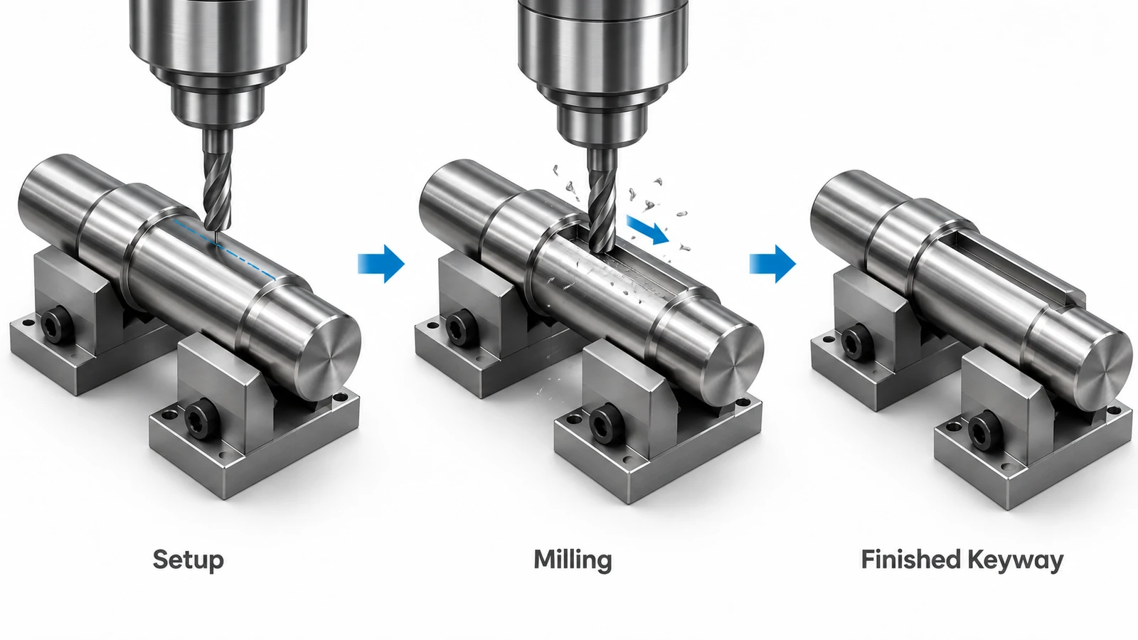
CNC milling is a practical method for producing many external shaft keyseats.
The following workflow illustrates the typical process.
Step 1: Review the Engineering Drawing
Before machining, identify:
- Shaft diameter
- Keyway width and depth
- Required slot length
- Slot position and orientation
- Material and hardness
- Dimensional and geometric tolerances
For a standard parallel keyway, confirm the applicable key and keyway standard.
For custom designs, ensure the specified geometry allows sufficient cutter access and proper key engagement.
Step 2: Secure and Align the Shaft
The shaft must be held securely to prevent rotation or movement during machining.
Suitable workholding arrangements may include:
- V-block fixtures
- Precision vises with suitable supports
- Collets or dedicated shaft fixtures
- Rotary-axis workholding for multi-feature components
The setup should establish a reliable relationship between the shaft centerline and the intended slot position.
Excessive clamping force should be avoided on thin-walled or easily distorted components.
Step 3: Select the Cutting Tool
Tool selection depends on the keyway width, length, depth, and material.
A suitable end mill can machine many straight external keyways.
A keyseat cutter may be preferable for geometries requiring a different cutter approach or slot form.
For demanding applications, tool diameter, flute length, rigidity, coating, and chip evacuation should be evaluated together.
A cutter matching the nominal slot width is not always the best choice. A smaller cutter with controlled finishing passes may offer better dimensional adjustment and wall finishing.
Step 4: Machine the Slot
A typical milling strategy uses controlled passes to remove material progressively.
For deeper slots, multiple axial depth increments help manage cutting forces.
When necessary, leave a small finishing allowance before machining the final slot walls.
Cutting speed, feed, and depth of cut should be selected according to material, cutter specifications, machine rigidity, and tool engagement.
There is no universal speed or feed suitable for every keyway.
Step 5: Deburr and Inspect
After milling, remove burrs from the slot edges without damaging the critical dimensions.
Inspect the finished keyway for:
- Slot width
- Depth
- Length
- Position
- Straightness and parallelism, where specified
- Surface defects and burrs
For high-precision assemblies, inspect both the keyway and mating components before final assembly.
Keyway Dimensions and Tolerances
Correct keyway dimensions are essential for reliable torque transmission and assembly.
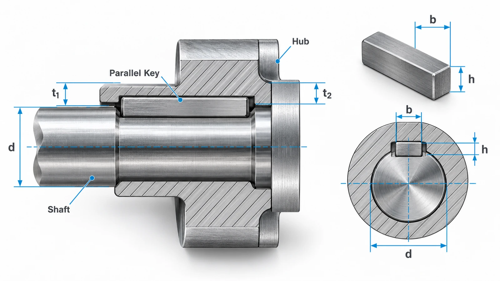
For a standard parallel-key connection, the principal dimensions include:
| Symbol | Dimension | Function |
|---|---|---|
| d | Shaft diameter | Determines the key size selection |
| b | Key width | Defines nominal key and slot width |
| h | Key height | Controls the key cross-section |
| t1 | Shaft keyseat depth | Depth of the slot in the shaft |
| t2 | Hub keyway depth | Depth of the slot in the mating hub |
The actual key and keyway dimensions should follow the design drawing and applicable standard.
Keyway Size Example
As an illustrative example, consider a 25 mm shaft using a standard parallel key.
Under common DIN 6885-1 dimension tables, a shaft diameter in the range above 22 mm and up to 30 mm is typically associated with an 8 × 7 mm parallel key.
A commonly listed nominal shaft keyseat depth for this configuration is 4.0 mm.
However, the designer must also verify the applicable keyway width tolerance, hub keyway depth, length, and fit requirements.
An 8 mm nominal keyway width does not mean every 8 mm measurement is automatically acceptable.
The tolerance zone depends on the specified fit and standard.
What Tolerances Matter Most?
Keyway width: Controls the fit between the key and slot and influences lateral play or assembly interference.
Keyway depth: Affects key seating and the available engagement with the mating component.
Keyway position: Determines alignment relative to the shaft axis and other functional features.
Parallelism and straightness: May be important for longer keyways and precision assemblies.
A keyway can have the correct nominal width and still cause assembly problems if its position or depth is incorrect.
The tolerance requirements should be selected according to the application’s torque, loading, assembly method, and functional needs.
How to Choose the Right Keyway Cutting Method
A practical method selection begins with the component geometry.
| Design Requirement | Recommended Starting Point |
|---|---|
| External keyway on a standard shaft | CNC milling |
| External keyway for a custom prototype | CNC milling |
| Internal keyway in a through-hole, repeated production | Broaching |
| Internal keyway in a blind bore | Specialized keyseating or slotting |
| Internal keyway with unusual geometry | Specialized milling, keyseating, or suitable EDM |
| Keyway in hardened conductive material | Evaluate wire EDM if wire access is feasible |
| Large hub with a deep internal keyway | Evaluate dedicated keyseating equipment |
These are starting recommendations, not universal rules.
For example, a blind-hole internal keyway may require a design review to determine whether sufficient tool clearance exists.
Similarly, wire EDM should only be selected when the wire can follow a physically achievable cutting path.
For precision shaft prototypes and other suitable components, CNC milling services offer a flexible approach to manufacturing custom slot features.
Common Keyway Machining Problems and Solutions
Even a relatively simple keyway can create problems if the toolpath, setup, or inspection method is unsuitable.
Keyway Width Is Oversized
Possible causes: Excessive cutter runout, tool deflection, incorrect tool compensation, or inaccurate setup.
Solutions: Inspect cutter condition and runout, verify tool offsets, and use appropriate finishing passes.
Keyway Depth Is Incorrect
Possible causes: Incorrect work offsets, inaccurate tool length compensation, or inconsistent datum selection.
Solutions: Establish the depth datum clearly, verify tool offsets, and inspect the first completed feature before continuing production.
Burrs Around the Slot
Possible causes: Tool wear, unsuitable cutting parameters, or material behavior.
Solutions: Optimize the cutting operation and apply controlled deburring without altering critical slot dimensions.
Poor Surface Finish or Chatter Marks
Possible causes: Inadequate shaft support, excessive tool overhang, unstable cutting conditions, or worn tooling.
Solutions: Improve workholding, shorten tool projection, adjust cutting parameters, and evaluate the finishing strategy.
Key Does Not Fit During Assembly
Possible causes: Incorrect keyway width or depth, burrs, unsuitable key dimensions, or misaligned mating features.
Solutions: Measure the shaft keyseat, hub keyway, and key separately. Check the complete assembly fit rather than modifying one component without identifying the cause.
For critical parts, dimensional inspection and verification of specified geometric requirements are important parts of the quality assurance process.
What Affects Keyway Cutting Cost?
The cost of keyway machining depends on more than the length of the slot.
Important factors include:
1. Keyway location: External keyways are generally easier to access than internal keyways.
2. Material: Hard steels, titanium alloys, and difficult-to-machine materials can increase tool wear and cycle time.
3. Slot geometry: Deep, narrow, long, or nonstandard keyways may require special tooling and additional passes.
4. Quantity: CNC milling can be economical for prototypes, while specialized broaching may offer lower per-part costs for suitable repeated production.
5. Tolerances and inspection: Tight dimensional requirements and additional verification can increase manufacturing effort.
For cost-effective manufacturing, specify standard key sizes where suitable, avoid unnecessarily restrictive tolerances, and select the process based on both part geometry and production quantity.
Conclusion
Keyway cutting is an important process for manufacturing mechanical power transmission components. The right method depends on whether the keyway is external or internal, the available tool access, material properties, tolerance requirements, and production volume.
CNC milling is a flexible solution for many external keyways, while broaching, keyseating, slotting, and EDM serve different internal or specialized applications.
Reliable keyway machining requires correct dimensions, stable workholding, controlled cutting conditions, and appropriate inspection.
Need custom CNC-machined shafts or precision components with keyway features? Send your drawings to YUANYI Precision Manufacturing for a manufacturability review and quotation.
Frequently Asked Questions
Yes, certain internal keyways can be produced using specialized cutters, attachments, or suitable machine configurations. However, ordinary end milling on a standard 3-axis machine generally cannot reach enclosed internal keyways.
A keyseat specifically refers to the slot in the shaft, while a keyway often refers to the slot in the hub. In everyday manufacturing terminology, keyway is frequently used for both features.
Yes. The method depends on material hardness, slot geometry, and required accuracy. Suitable carbide machining, grinding, or EDM may be considered depending on the application.
Yes, but it requires a compatible process and sufficient tool clearance. Specialized keyseating or slotting may be suitable. Conventional through-broaching and wire EDM cannot be assumed to work in a closed-bottom bore.
A keyway removes material and introduces geometric discontinuities that can create stress concentrations. Its effect depends on shaft size, slot geometry, material, torque, and cyclic loading. Critical shaft designs should be evaluated for strength and fatigue requirements.



