

Material stiffness describes how strongly a material resists elastic deformation when a force is applied. A stiffer material bends, stretches, or compresses less under the same load.
Stiffness is commonly associated with Young’s modulus (E). Materials with a higher Young’s modulus generally deform less elastically. However, stiffness is not the same as strength: stiffness determines how much a part deforms, while strength determines how much stress it can withstand before yielding or failing.
For engineers and product designers, this distinction is important when selecting materials and designing CNC machined parts that must maintain dimensional accuracy under load.
What Is Stiffness of Material?
Material stiffness is the ability of a material to resist elastic deformation under load.
Imagine two bars with identical dimensions: one made from steel and the other from aluminum. Under the same force, the aluminum bar will generally deform more because aluminum has a lower elastic modulus.
As long as the material remains within its elastic region, it returns to its original shape after the load is removed.
In simple terms:
Higher stiffness = less elastic deformation under the same conditions.
Stiffness is especially important for machine structures, precision fixtures, long shafts, robotic arms, thin-wall housings, aerospace components, and other parts where excessive deflection can affect performance or accuracy.
A component can therefore be strong enough not to break but still be unsuitable if it bends too much during use.
How Is Material Stiffness Measured?
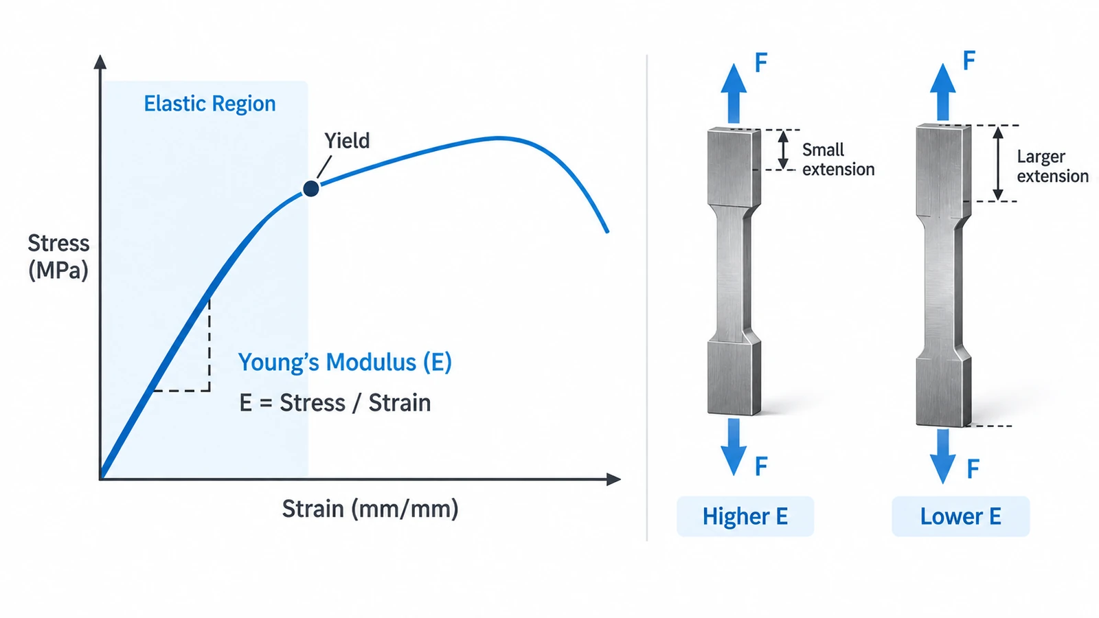
The most common property used to describe material stiffness is Young’s modulus, also called the modulus of elasticity.
For a material under tensile or compressive loading:
E = σ / ε
Where:
- E = Young’s modulus
- σ = stress
- ε = strain
Stress describes force per unit area, while strain describes the change in length relative to the original length.
Young’s modulus is typically expressed in GPa (gigapascals). A higher value means more stress is required to produce the same amount of elastic strain.
For example, steel has a Young’s modulus of approximately 200 GPa, while aluminum is around 69 GPa. For identical geometry and loading conditions, the steel component will therefore deform less.
Young’s Modulus and the Stress-Strain Curve
Young’s modulus corresponds to the slope of the initial linear portion of a material’s stress-strain curve.
Within this region, deformation is elastic. When the load is removed, the material returns approximately to its original dimensions.
Once stress reaches the yield region, permanent deformation begins. This is where strength-related properties become increasingly important.
Young’s Modulus of Common Engineering Materials
The following values provide a general comparison of materials commonly used in engineering and CNC machining.
| Material | Typical Young’s Modulus |
|---|---|
| Carbon Steel | ~200–210 GPa |
| Stainless Steel | ~190–200 GPa |
| Copper | ~110–130 GPa |
| Titanium Alloys | ~105–115 GPa |
| Brass | ~90–110 GPa |
| Aluminum Alloys | ~68–72 GPa |
| Unfilled PEEK | ~3.5–4.0 GPa |
| POM / Acetal | ~2.5–3.5 GPa |
| ABS | ~1.5–2.5 GPa |
Values are approximate and can vary with alloy, grade, temperature, reinforcement, and test conditions.
One important point is that higher strength does not necessarily mean higher stiffness.
For example, different aluminum alloys can have substantially different yield strengths while their Young’s modulus remains relatively close to 69–72 GPa.
Therefore, replacing one aluminum alloy with a higher-strength aluminum alloy will not necessarily solve a stiffness or deflection problem.
Stiffness vs. Strength: What Is the Difference?
Stiffness and strength answer two different engineering questions:
Stiffness: How much will the component deform?
Strength: How much stress can the component withstand before permanent deformation or failure?
| Factor | Stiffness | Strength |
|---|---|---|
| Main concern | Elastic deformation | Yielding or failure |
| Common property | Young’s modulus | Yield / tensile strength |
| Typical question | How much will it bend? | Will it permanently deform or break? |
| Higher value means | Less elastic deformation | Greater stress capacity |
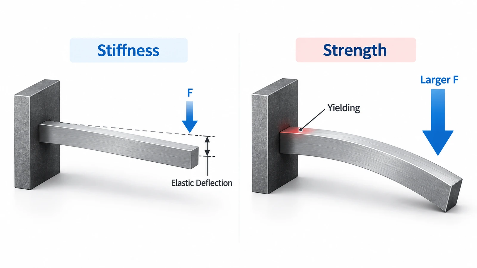
Consider a precision bracket supporting an optical sensor.
The bracket may easily support the load without yielding, but if it bends enough to misalign the sensor, the design can still fail functionally. In this situation, stiffness rather than ultimate strength controls the design.
A highly loaded shaft, pin, or bolt, on the other hand, must also have sufficient strength to avoid permanent deformation or fracture.
Good mechanical design considers both properties.
Stiffness vs. Hardness vs. Strength
These three properties are related to different types of material behavior.
Stiffness describes resistance to elastic deformation.
Strength describes the ability to withstand stress before yielding or failure.
Hardness describes resistance to localized surface deformation such as indentation, scratching, and wear.
For example, heat treatment can significantly increase the hardness and strength of certain steels while producing relatively little change in their Young’s modulus.
Therefore:
Harder does not necessarily mean stiffer, and stronger does not necessarily mean stiffer.
The correct property depends on the type of deformation or failure the component must resist.
Material Stiffness vs. Structural Stiffness
This distinction is particularly important in mechanical design.
Material stiffness is an inherent material property and is commonly represented by Young’s modulus.
Structural stiffness describes how resistant an entire component is to deformation.
Structural stiffness depends on more than material alone. Important factors include:
- Elastic modulus
- Cross-sectional geometry
- Wall thickness
- Component length
- Ribs and flanges
- Load direction
- Support conditions
This means two components made from exactly the same material can have dramatically different stiffness.
Why Geometry Matters
Consider a flat aluminum sheet.
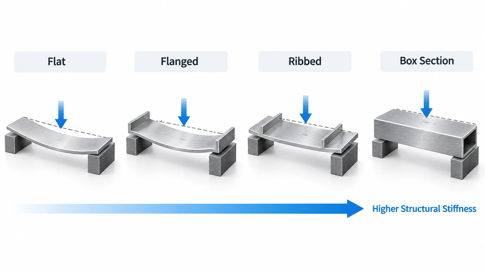
If both long edges are bent upward to create flanges, the Young’s modulus of the aluminum has not changed. However, the sheet becomes much harder to bend because its cross-sectional geometry has changed.
Adding ribs, corrugations, channels, or box sections can increase structural stiffness even further without requiring a proportional increase in material.
This principle is widely used in sheet metal enclosures, aerospace structures, automotive panels, machine frames, robotic components, and CNC machined housings.
Therefore, when a component deflects too much, changing materials is not always the most efficient solution.
How Does Part Geometry Affect Stiffness?
For components subjected to bending, stiffness depends on both the material and the cross-sectional geometry.
In simplified form:
Bending stiffness ∝ E × I
Where:
- E = Young’s modulus of the material
- I = second moment of area of the cross-section
The E term comes from the material, while the I term comes from geometry.
This is why changing the cross-section of a part can sometimes improve stiffness more effectively than simply switching to a stronger material.
For example, increasing section height, adding ribs, creating flanges, or using box-shaped sections moves material into positions where it resists bending more effectively.
Unsupported length is also important. Long, slender components generally deflect much more than shorter components under similar loads, so additional support can significantly improve structural rigidity.
How to Increase Part Stiffness
When a component is too flexible, engineers have several options besides simply adding more material.
| Method | Why It Helps |
|---|---|
| Increase section height | Improves resistance to bending |
| Add ribs or gussets | Reinforces flexible areas with limited added weight |
| Add flanges | Improves bending resistance by changing the cross-section |
| Use box or tubular sections | Provides high bending and torsional stiffness |
| Reduce unsupported length | Reduces deflection under load |
| Increase local wall thickness | Reinforces critical areas without thickening the entire part |
| Use a higher-modulus material | Reduces elastic deformation when geometry cannot be changed |
In many lightweight designs, optimizing geometry provides a better stiffness-to-weight result than simply increasing wall thickness everywhere.
Why Does Stiffness Matter in CNC Machining?
Stiffness affects not only how a finished component performs but also how accurately it can be machined.
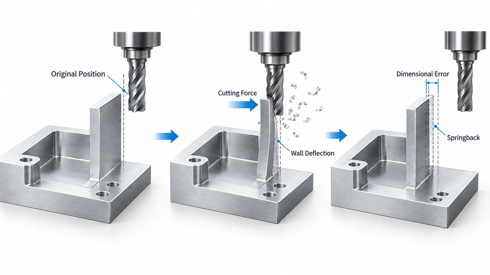
During CNC machining, cutting tools generate forces against the workpiece. If the workpiece is flexible, these forces can temporarily deflect it.
The cutting tool may then remove material while the part is slightly displaced from its intended position. After the cutting force disappears, the component springs back.
The result can be dimensional error even when the CNC machine itself is highly accurate.
Thin-Wall Parts
Thin walls are particularly sensitive to cutting forces.
For example, a thin aluminum wall may deflect slightly away from an end mill during finishing. After the tool passes, the wall springs back, causing the actual wall thickness or profile to differ from the programmed toolpath.
Possible problems include:
- Wall thickness variation
- Dimensional errors
- Chatter
- Poor surface finish
- Out-of-tolerance features
Machining sequence, tool engagement, fixture support, and finishing parameters therefore become important for thin-wall components.
Long Shafts
Long, slender shafts can bend away from the cutting tool during turning.
This can produce taper, diameter variation, vibration, and poor surface finish.
Depending on the part geometry, tailstocks, steady rests, optimized cutting parameters, or different machining sequences may be required.
Deep Pockets
Deep pockets often leave tall, thin walls around the machined cavity.
As material is removed, the remaining structure becomes less rigid. Cutting forces can then cause wall vibration or deflection during finishing.
This is one reason deep-pocket and thin-wall components require careful machining strategies.
Engineering Plastics
Engineering plastics such as POM and PEEK have much lower elastic moduli than metals such as aluminum and steel.
They can therefore deform more easily under clamping and cutting forces.
Fixture pressure, cutting heat, machining sequence, and inspection conditions should be carefully controlled when tight tolerances are required.
Does Heat Treatment Increase Material Stiffness?
Usually, not significantly.
Heat treatment can substantially change:
- Hardness
- Yield strength
- Tensile strength
- Wear resistance
However, its effect on Young’s modulus is generally much smaller.
For example, heat treating steel may make it significantly harder and stronger without making it proportionally stiffer in the elastic range.
Similarly, different tempers of an aluminum alloy can have very different yield strengths while maintaining relatively similar elastic moduli.
If excessive elastic deflection is the problem, engineers should therefore examine geometry and elastic modulus rather than assuming higher hardness or strength will solve it.
How to Choose Between Stiffness and Strength
For precision fixtures, machine structures, robotic arms, sensor mounts, and long brackets, stiffness may control the design because excessive deflection can affect accuracy before the material approaches its strength limit.
For highly loaded shafts, pins, bolts, and structural connections, yield and tensile strength may become more critical.
Lightweight applications such as aerospace and robotics often require engineers to balance stiffness, strength, weight, geometry, manufacturability, and cost rather than optimizing a single material property.
Stiffness in CNC Part Design
For CNC machined components, stiffness should be considered during both part design and manufacturing.
A component may have sufficient stiffness in its finished assembly but become flexible during machining as pockets, slots, and other features are progressively removed.
Important design and manufacturing considerations include:
- Final wall thickness
- Pocket depth
- Rib placement
- Feature aspect ratios
- Unsupported sections
- Clamping locations
- Material elastic modulus
- Expected cutting forces
When tight tolerances are required, machining strategy becomes equally important.
Roughing and finishing operations may be separated, material can be removed more symmetrically, cutting forces can be reduced during finishing, and fixtures can support flexible areas of the workpiece.
These measures help reduce elastic deformation and improve dimensional consistency.
Conclusion
Material stiffness describes resistance to elastic deformation and is commonly characterized by Young’s modulus. However, the stiffness of a finished component depends on both its material and its geometry.
Section height, ribs, flanges, wall thickness, unsupported length, and support conditions can all significantly affect how much a part deflects.
For CNC machined components, stiffness also affects manufacturability. Understanding the interaction between material properties, part geometry, cutting forces, and fixturing helps engineers design components that maintain both dimensional accuracy and reliable performance.
FAQs
Material stiffness is the resistance of a material to elastic deformation under load. Young’s modulus is commonly used to quantify stiffness under tensile or compressive loading.
No. Stiffness determines how much a material elastically deforms under load, while strength describes how much stress it can withstand before yielding or failing.
Yes. Most steels have a Young’s modulus of approximately 200 GPa, compared with about 69 GPa for aluminum. For identical geometry and loading conditions, steel therefore generally experiences less elastic deformation.
No. Young’s modulus measures stiffness rather than strength. Materials can have similar elastic moduli but very different yield or tensile strengths.
Part stiffness can often be improved by increasing section height, adding ribs or gussets, reducing unsupported spans, using flanges or box-shaped sections, increasing local wall thickness, or selecting a material with a higher elastic modulus.



