

Welding defects are imperfections that can affect the strength, appearance, dimensional accuracy, or reliability of a welded joint. Common examples include cracks, porosity, undercut, slag inclusions, lack of fusion, incomplete penetration, and distortion.
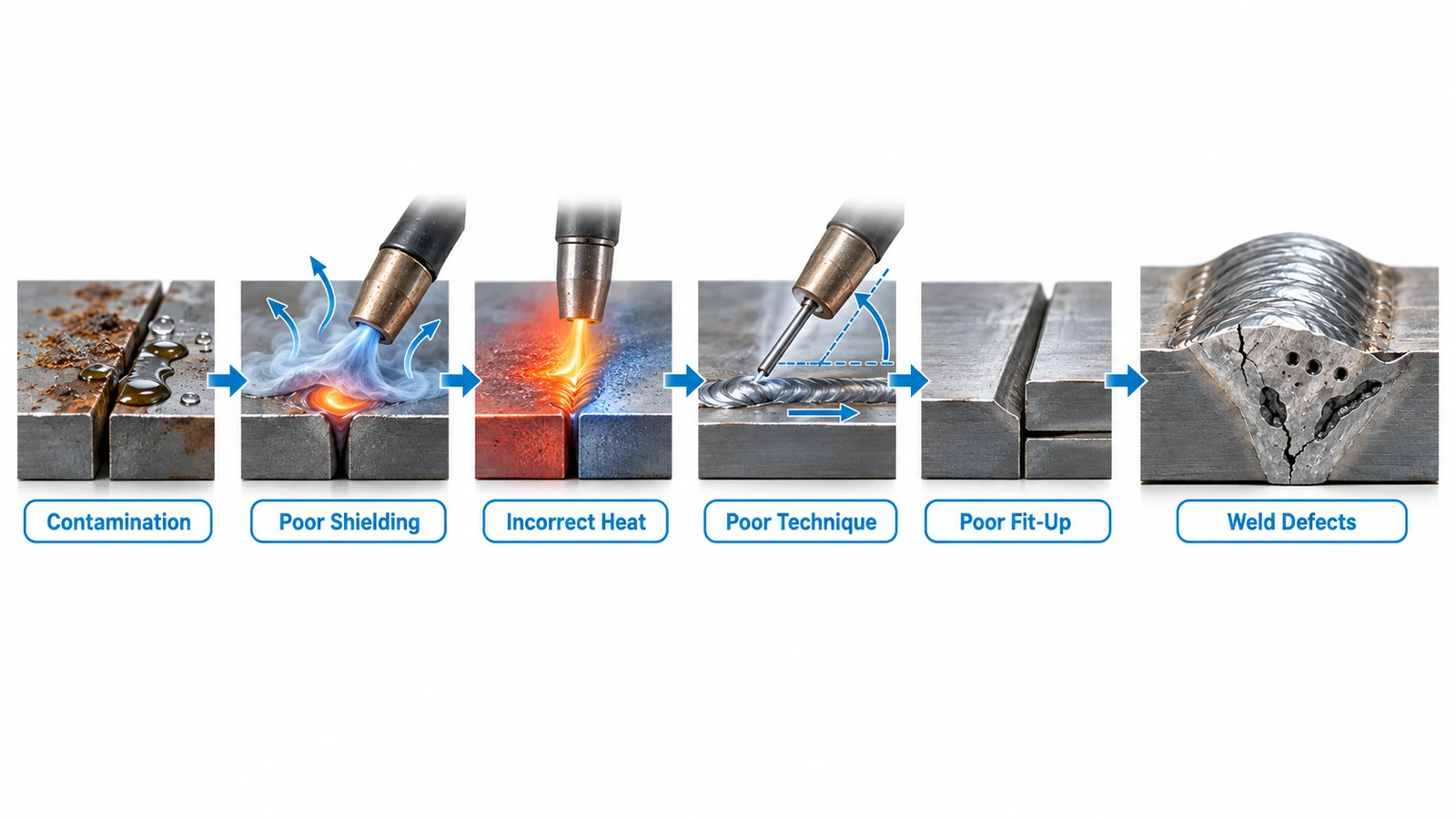
Most weld defects are related to improper heat input, contamination, poor shielding, incorrect welding parameters, joint fit-up, or uneven heating and cooling. Some defects are visible on the surface, while others remain hidden inside the weld and require non-destructive testing (NDT) to detect.
Understanding what different welding defects look like, why they occur, and how to prevent them helps reduce rework and improve the quality of fabricated metal parts.
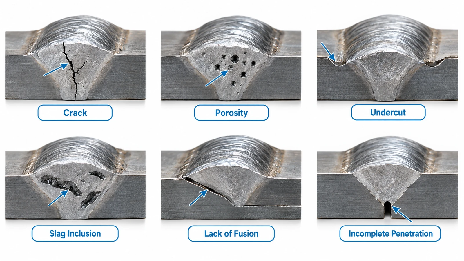
What Is a Welding Defect?
A welding defect is an unacceptable imperfection in or around a welded joint that does not meet the required quality or acceptance criteria.
Defects may occur on the weld surface, at the weld root, along the fusion boundary, or inside the weld metal. Depending on their type and severity, they can reduce joint strength, create stress concentrations, affect fatigue life, or cause dimensional problems in the finished assembly.
However, not every weld imperfection automatically makes a component unacceptable.
Welding Defect vs Welding Discontinuity
A weld discontinuity is an interruption or irregularity in the normal structure of a weld. A weld defect generally refers to a discontinuity that exceeds the applicable acceptance criteria.
| Term | Meaning |
|---|---|
| Weld Discontinuity | A deviation from the ideal weld condition |
| Weld Imperfection | An irregularity in weld geometry or structure |
| Weld Defect | An imperfection that exceeds applicable acceptance limits |
Whether an imperfection is acceptable depends on factors such as its size, location, quantity, component application, and the welding standard or specification being used.
What Causes Welding Defects?
Although different weld defects have different characteristics, many originate from a relatively small number of process problems.
Incorrect Heat Input
Excessive heat can cause burn-through, excessive penetration, undercut, and distortion. Insufficient heat may prevent the base metal from melting properly, resulting in lack of fusion or incomplete penetration.
Contaminated Surfaces
Oil, moisture, rust, paint, oxides, and other contaminants can introduce gases or foreign material into the molten weld pool. This increases the risk of porosity, inclusions, and poor fusion.
Poor Shielding
In MIG, TIG, and other gas-shielded welding processes, inadequate shielding allows atmospheric gases to contaminate the weld pool. Incorrect gas flow, drafts, damaged hoses, or improper torch positioning can all affect shielding performance.
Incorrect Welding Technique
Travel speed, torch angle, arc length, electrode position, and filler deposition all influence weld quality. Incorrect technique can produce undercut, overlap, spatter, and incomplete fusion.
Poor Joint Design or Fit-Up
Incorrect root gaps, misalignment, insufficient bevel angles, or inconsistent joint preparation can make proper penetration and fusion difficult.
Uneven Heating and Cooling
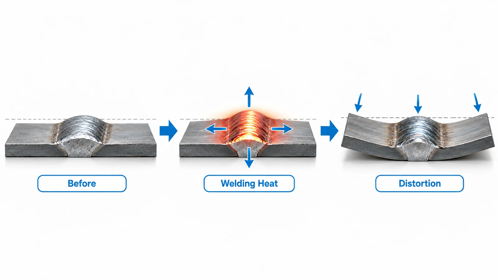
Welding introduces highly localized heat. As the weld and surrounding material cool and contract, residual stresses can develop, leading to distortion or cracking.
12 Common Types of Welding Defects
The following defects are among the most common problems found in welded metal components.
1. Weld Cracks
Weld cracks are among the most serious welding defects because even a small crack can propagate under load and eventually cause joint failure.
Cracks may occur in the weld metal, heat-affected zone (HAZ), weld toe, or base material. Depending on when they form, they may be classified as hot cracks or cold cracks.
Common causes:
- High residual stress
- Rapid cooling
- Hydrogen contamination
- Improper filler material
- High carbon equivalent in the base material
- Poor joint design
How to prevent weld cracks: Use suitable filler materials, control heat input and cooling rate, keep electrodes and joint surfaces dry, and use preheating or post-weld heat treatment when required by the material and welding procedure.
2. Porosity
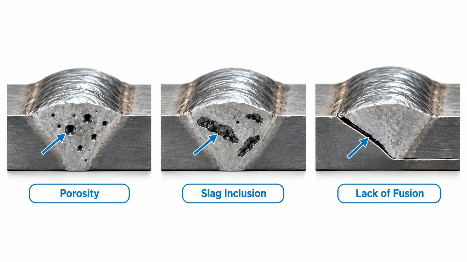
Porosity consists of gas pockets trapped inside the weld metal during solidification. It may appear as individual pores, clusters, or elongated cavities.
Surface porosity is often visible as small holes, while internal porosity may require radiographic or ultrasonic inspection.
Common causes:
- Oil, grease, rust, or moisture
- Inadequate shielding gas
- Excessive arc length
- Incorrect gas flow
- Contaminated filler material
How to prevent porosity: Clean and dry the joint before welding, maintain proper shielding gas coverage, inspect gas lines for leaks, use clean filler materials, and maintain suitable arc length and welding parameters.
3. Undercut
Undercut is a groove melted into the base metal along the edge of the weld that is not completely filled with weld metal.
Because undercut reduces the effective cross-section of the material and creates a stress concentration, severe undercut can reduce fatigue performance.
Common causes:
- Excessive welding current
- Excessive travel speed
- Long arc length
- Incorrect electrode or torch angle
- Poor filler placement
How to prevent undercut: Reduce excessive heat input, maintain appropriate travel speed and arc length, and position the torch or electrode so that sufficient filler reaches the weld toe.
4. Slag Inclusion
Slag inclusions occur when non-metallic solid material becomes trapped inside the weld.
They are particularly associated with welding processes that generate slag, such as shielded metal arc welding (SMAW) and flux-cored arc welding (FCAW).
Common causes:
- Failure to remove slag between passes
- Incorrect electrode angle
- Low heat input
- Poor joint preparation
- Improper welding technique
How to prevent slag inclusions: Clean each weld pass thoroughly before depositing the next one, maintain proper heat input, and ensure the joint provides sufficient access for complete fusion.
5. Lack of Fusion
Lack of fusion occurs when the weld metal does not properly fuse with the base metal or with a previous weld pass.
Unlike porosity, which involves trapped gas, lack of fusion creates an unfused interface that can significantly weaken the joint.
Common causes:
- Insufficient heat input
- Excessive travel speed
- Surface contamination
- Incorrect torch angle
- Poor joint preparation
How to prevent lack of fusion: Remove oxides and contamination before welding, use sufficient heat to melt the joint surfaces, maintain an appropriate travel speed, and direct the arc toward the areas requiring fusion.
6. Incomplete Penetration
Incomplete penetration occurs when the weld does not extend completely through the intended joint thickness or does not properly fuse at the root.
It is commonly associated with groove and butt joints.
Common causes:
- Insufficient heat input
- Root gap that is too small
- Improper groove angle
- Excessive travel speed
- Incorrect electrode size or positioning
How to prevent incomplete penetration: Use suitable joint geometry and root spacing, maintain sufficient heat input, and select welding parameters appropriate for the material thickness and joint configuration.
7. Overlap
Overlap occurs when molten weld metal flows onto the base material without properly fusing with it.
It usually appears as weld metal extending beyond the weld toe and resting on the base metal surface.
Common causes:
- Excessive filler metal
- Slow travel speed
- Incorrect torch or electrode angle
- Insufficient heat at the weld toe
How to prevent overlap: Control filler deposition, maintain appropriate travel speed, and direct heat toward the base material to achieve proper fusion at the weld edges.
8. Weld Spatter
Spatter consists of small droplets of molten metal that are expelled from the welding arc and adhere to the surrounding surface.
Minor spatter may primarily affect appearance and increase cleanup time. Excessive spatter can also indicate unstable welding conditions.
Common causes:
- Excessive current or voltage
- Incorrect polarity
- Unstable arc
- Contaminated surfaces
- Improper shielding or wire feed settings
How to prevent spatter: Use stable welding parameters, clean the workpiece, maintain the correct arc length, and optimize voltage, current, and wire feed according to the welding process.
9. Burn-Through
Burn-through occurs when excessive heat melts completely through the base material and creates an unintended hole.
It is especially common when welding thin sheet metal.
Common causes:
- Excessive welding current
- Slow travel speed
- Large root gap
- Concentrated heat input
- Poor control when welding thin material
How to prevent burn-through: Reduce heat input, increase travel speed where appropriate, improve joint fit-up, and use backing bars, heat sinks, or pulsed welding techniques when suitable.
10. Underfill and Excess Reinforcement
Underfill occurs when the weld surface remains below the adjacent base material. Excess reinforcement is the opposite condition, where too much weld metal is deposited above the joint.
Both conditions affect weld geometry.
Common causes:
- Incorrect filler deposition
- Improper travel speed
- Incorrect joint preparation
- Poor control of welding parameters
How to prevent these defects: Maintain consistent filler deposition and travel speed while controlling weld bead size according to the joint geometry and welding procedure.
11. Crater Cracks
A crater forms at the end of a weld when the arc is stopped. If this depression is not properly filled before the weld pool solidifies, shrinkage stresses can produce a crater crack.
Crater cracks can become initiation points for larger cracks under cyclic or structural loading.
Common causes:
- Abrupt arc termination
- Insufficient filler metal at the weld end
- Rapid solidification
- High shrinkage stress
How to prevent crater cracks: Fill the crater before terminating the arc and use appropriate crater-fill or downslope functions when supported by the welding equipment.
12. Welding Distortion
Distortion occurs when uneven heating and cooling cause a welded component to change shape.
Unlike defects contained directly inside the weld, distortion affects the geometry of the overall part or assembly. Common forms include angular distortion, bowing, twisting, and longitudinal or transverse shrinkage.
Common causes:
- High heat input
- Uneven weld placement
- Poor welding sequence
- Insufficient fixturing
- Large or concentrated welds
How to prevent welding distortion: Use balanced welding sequences, minimize unnecessary heat input, apply suitable fixtures or tack welds, and design joints to reduce excessive weld volume.
For components that require machining after welding, distortion control is particularly important because deformation can affect machining allowance, datum positions, hole locations, and final dimensional accuracy.
How Are Welding Defects Detected?
Some welding defects are easy to see, while others are hidden below the surface. Inspection methods are therefore selected according to the type of defect, material, component geometry, and quality requirements.
| Inspection Method | Typical Defects Detected |
|---|---|
| Visual Testing (VT) | Undercut, overlap, spatter, surface cracks, poor bead geometry |
| Dye Penetrant Testing (PT) | Fine surface-breaking cracks and porosity |
| Magnetic Particle Testing (MT) | Surface and near-surface cracks in ferromagnetic materials |
| Ultrasonic Testing (UT) | Internal cracks, lack of fusion, inclusions and other internal discontinuities |
| Radiographic Testing (RT) | Internal porosity, slag inclusions and penetration-related defects |
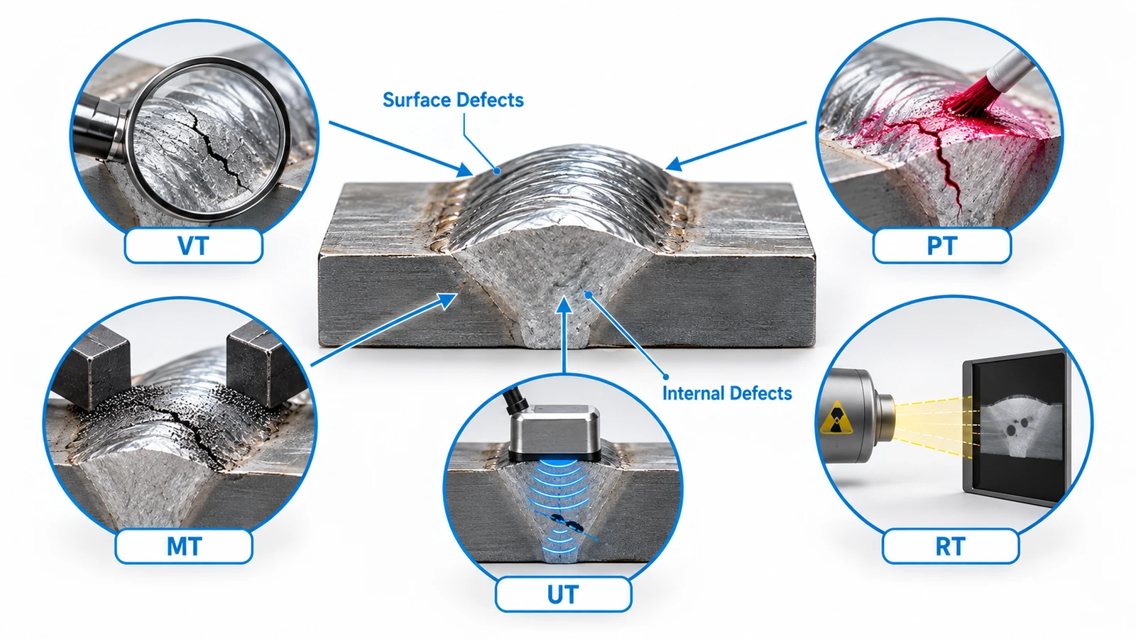
Visual inspection is usually the first step because it is fast and inexpensive. However, critical welds may require one or more NDT methods to evaluate defects that cannot be identified from the surface alone.
The appropriate inspection method should be selected according to the component requirements and applicable welding specification.
How to Prevent Welding Defects
Preventing defects is generally more efficient than repairing completed welds. Although each welding process has its own requirements, several practices help reduce defects across many applications.
Prepare the joint properly. Remove rust, oil, paint, moisture, oxides, and other contaminants before welding.
Control joint fit-up. Maintain suitable root gaps, alignment, bevel angles, and joint geometry.
Use appropriate welding parameters. Current, voltage, travel speed, wire feed, arc length, and heat input should match the material, thickness, joint design, and welding process.
Maintain proper shielding. Check gas flow, hoses, torch condition, and protection from drafts when using gas-shielded processes.
Control heat input and welding sequence. Excessive or uneven heat can increase the risk of cracking and distortion.
Inspect during production. Checking joint preparation, intermediate passes, and completed welds can identify problems before additional manufacturing work is performed.
For precision components, welding quality should also be considered together with downstream processes such as CNC machining. Residual stress and weld distortion can influence datums, tolerances, flatness, hole positions, and other machined features.
Conclusion
Welding defects can result from contamination, incorrect heat input, poor shielding, improper joint preparation, welding technique, or uneven thermal contraction. Recognizing defects such as cracks, porosity, undercut, slag inclusions, lack of fusion, incomplete penetration, and distortion makes it easier to identify their causes and prevent them during production.
For welded components that require subsequent CNC machining, controlling welding distortion and residual stress is also important for maintaining machining allowances and final dimensional accuracy. Considering welding, inspection, and machining as part of the same manufacturing process helps produce more consistent finished components.
FAQs
Porosity, undercut, spatter, incomplete fusion, and slag inclusions are among the commonly encountered welding defects. The frequency of each defect depends on the welding process, material, joint design, and operator technique.
Porosity consists of gas trapped in the solidifying weld metal, while slag inclusions are solid non-metallic materials trapped inside the weld. Their causes and appearance differ, although both can reduce weld quality when they exceed acceptable limits.
Internal porosity, slag inclusions, internal cracks, lack of fusion, and incomplete penetration may not always be visible from the surface. Ultrasonic or radiographic testing may be required depending on the defect and component.
Many welding defects can be repaired by removing the affected weld material and rewelding the area using an approved procedure. Whether repair is permitted depends on the material, defect severity, component requirements, and applicable welding standard.
Post-weld cracking may result from residual stress, hydrogen, rapid cooling, material composition, joint restraint, or unsuitable welding procedures. Proper material preparation, heat control, filler selection, and preheating or post-weld treatment where required can reduce the risk.



