

Machine screws are threaded fasteners commonly used to assemble metal components, machinery, electronics, and precision equipment. They are available in different diameters, thread pitches, lengths, and head styles, making accurate size selection essential for a reliable fit.
A machine screw size chart helps you identify nominal thread diameters, compare US and metric sizes, and select the correct thread pitch. For example, a #8-32 screw has a nominal diameter of 0.164 inches (4.17 mm) and 32 threads per inch, while an M4 × 0.7 screw has a nominal diameter of 4 mm and a 0.7 mm thread pitch.
What Is a Machine Screw?
A machine screw is a threaded fastener designed to engage a compatible internal thread, usually in a tapped hole or nut. Unlike many wood screws and self-tapping screws, standard machine screws generally do not create their own mating threads during installation.
Machine screws typically have uniform external threads and are available with different head styles and drive types.
They are commonly used in:
- Mechanical assemblies and industrial equipment
- Electronic devices and electrical enclosures
- Automotive components
- Precision instruments and CNC-machined parts
- Brackets, covers, and metal housings
Machine screws are often smaller than conventional bolts, but there is no universal diameter cutoff separating the two. Their classification also depends on the applicable product standard and head design.
How to Read Machine Screw Sizes
Machine screw specifications identify the thread diameter, thread pitch, and length. However, US and metric systems use different sizing conventions.
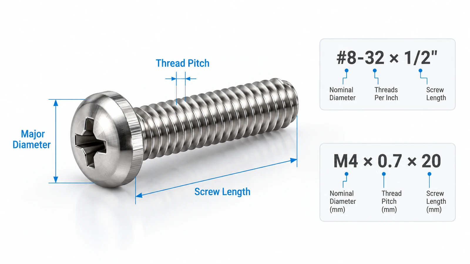
US Machine Screw Sizes
Consider this specification:
#8-32 × 1/2″
| Marking | Meaning |
|---|---|
| #8 | Nominal screw size, 0.164″ diameter |
| 32 | 32 threads per inch (TPI) |
| 1/2″ | Nominal screw length, 0.5 inches |
The #8 designation does not mean the screw has an 8 mm diameter. Numbered screw sizes follow the Unified inch thread system.
A #8-32 screw uses a coarse-thread designation (UNC), while a #8-36 screw uses a fine-thread designation (UNF).
Two screws with the same nominal diameter but different thread pitches are not interchangeable in an existing tapped hole.
Metric Machine Screw Sizes
Metric machine screws use the letter M followed by the nominal diameter in millimeters.
For example:
M4 × 0.7 × 20
| Marking | Meaning |
|---|---|
| M4 | Nominal thread diameter of 4 mm |
| 0.7 | Thread pitch of 0.7 mm |
| 20 | Nominal screw length of 20 mm |
Thread pitch is the axial distance between adjacent thread crests.
For standard metric coarse threads, the pitch is sometimes omitted. Therefore, M4 × 20 commonly indicates an M4 coarse-thread screw with a 0.7 mm pitch.
For fine-thread screws, the pitch should be specified explicitly.
US Machine Screw Size Chart
US machine screws typically use Unified National Coarse (UNC) or Unified National Fine (UNF) threads.
The following chart lists common nominal diameters and corresponding thread counts.
| Screw Size | Major Diameter (in) | Major Diameter (mm) | UNC (TPI) | UNF (TPI) |
|---|---|---|---|---|
| #0 | 0.060 | 1.524 | — | 80 |
| #1 | 0.073 | 1.854 | 64 | 72 |
| #2 | 0.086 | 2.184 | 56 | 64 |
| #3 | 0.099 | 2.515 | 48 | 56 |
| #4 | 0.112 | 2.845 | 40 | 48 |
| #5 | 0.125 | 3.175 | 40 | 44 |
| #6 | 0.138 | 3.505 | 32 | 40 |
| #8 | 0.164 | 4.166 | 32 | 36 |
| #10 | 0.190 | 4.826 | 24 | 32 |
| #12 | 0.216 | 5.486 | 24 | 28 |
| 1/4″ | 0.250 | 6.350 | 20 | 28 |
| 5/16″ | 0.3125 | 7.938 | 18 | 24 |
| 3/8″ | 0.375 | 9.525 | 16 | 24 |
Note: Dimensions are nominal values based on Unified thread conventions. Actual acceptable major diameters depend on thread class and tolerances. A dash indicates that a corresponding standard UNC designation is not listed. Verify critical dimensions against ASME B1.1.
UNC vs. UNF Machine Screws
UNC and UNF threads differ primarily in thread pitch.
UNC (Unified National Coarse) uses fewer threads per inch for a given nominal diameter. Coarse threads are often preferred for general assembly, especially when ease of installation and resistance to cross-threading are important.
UNF (Unified National Fine) uses more threads per inch. Fine threads can provide finer axial adjustment and may be advantageous for certain applications involving limited thread engagement or vibration-resistant joint designs.
However, vibration resistance depends on the entire fastening system, including preload and locking method—not simply whether the thread is coarse or fine.
For example:
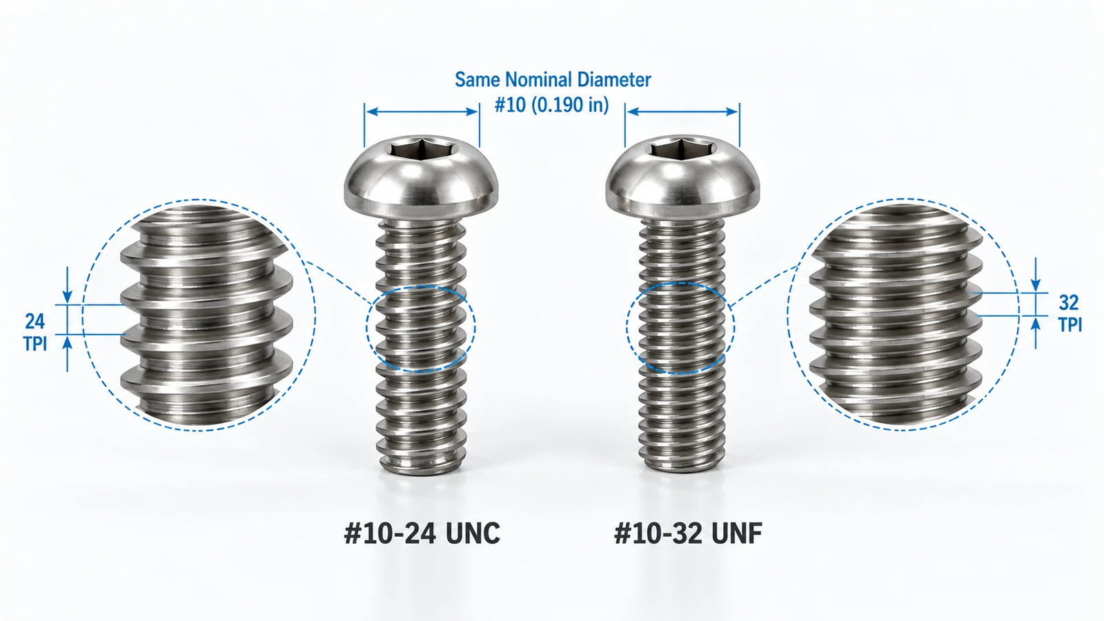
- #10-24 UNC: 24 threads per inch
- #10-32 UNF: 32 threads per inch
Both have the same nominal major diameter of 0.190 inches, but their thread pitches differ.
Metric Machine Screw Size Chart
Metric machine screws follow ISO metric thread conventions. The table below lists common nominal sizes and coarse-thread pitches, along with selected fine-thread alternatives.
| Screw Size | Major Diameter (mm) | Coarse Pitch (mm) | Common Fine Pitch (mm) |
|---|---|---|---|
| M2 | 2.0 | 0.40 | 0.25 |
| M2.5 | 2.5 | 0.45 | 0.35 |
| M3 | 3.0 | 0.50 | 0.35 |
| M4 | 4.0 | 0.70 | 0.50 |
| M5 | 5.0 | 0.80 | 0.50 |
| M6 | 6.0 | 1.00 | 0.75 |
| M8 | 8.0 | 1.25 | 1.00 |
| M10 | 10.0 | 1.50 | 1.25 |
| M12 | 12.0 | 1.75 | 1.50 |
Note: These are nominal dimensions. Fine-thread availability depends on the specific fastener standard and supplier. Other fine pitches may also exist. Refer to ISO 261 and ISO 724 for metric thread specifications.
Are Metric and US Machine Screws Interchangeable?
Metric and US machine screws are generally not interchangeable, even when their diameters are similar.
For example:
- M4: nominal diameter 4.00 mm, coarse pitch 0.70 mm
- #8-32 UNC: nominal diameter 4.166 mm, pitch approximately 0.794 mm
Although their diameters are close, their thread pitches differ.
Attempting to install one into a threaded hole designed for the other may damage the threads.
Always match the nominal diameter, thread pitch, and thread form rather than relying only on the measured outside diameter.
How to Measure Machine Screw Diameter, Pitch, and Length
Accurate measurement is important when identifying an unknown screw or replacing an existing fastener.
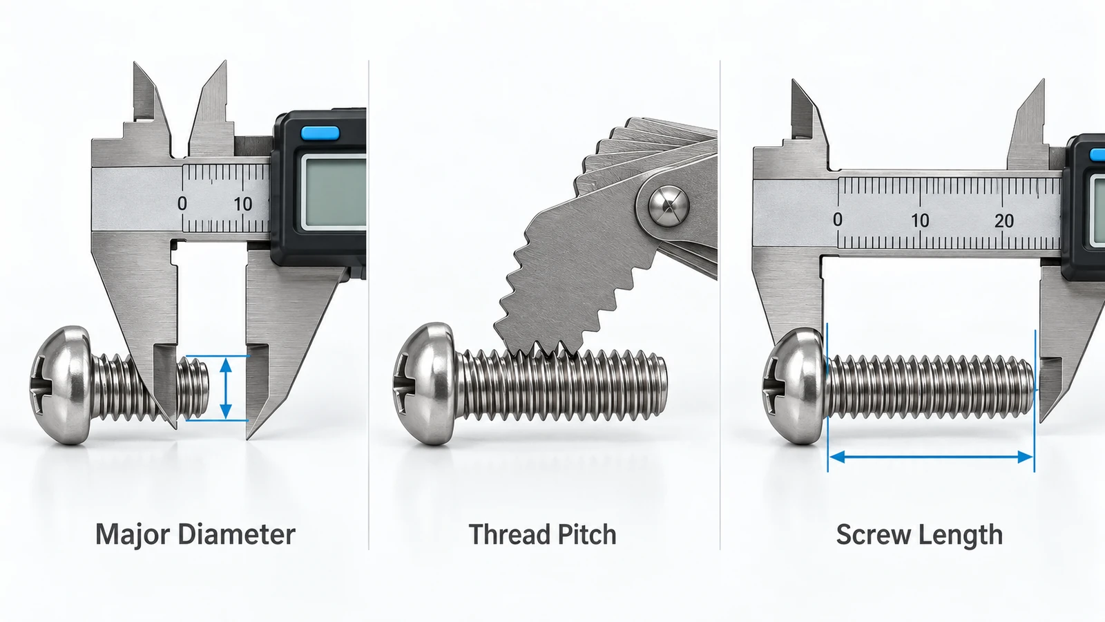
Three primary dimensions must be checked: diameter, thread pitch, and length.
1. Measure the Major Diameter
Use a caliper to measure across the outermost thread crests.
For external threads, the major diameter is the largest thread diameter.
A screw measuring approximately 4.0 mm across the thread crests may be an M4 screw, while one near 4.17 mm may be a #8 screw.
However, measurement alone cannot establish the exact thread designation because manufacturing tolerances and thread wear can affect the result.
2. Identify the Thread Pitch
For metric screws, measure the distance between adjacent thread crests using a thread pitch gauge.
For US screws, count the number of threads per inch or use an inch-thread pitch gauge.
For example:
- M5 × 0.8: 0.8 mm between adjacent thread crests
- #10-24: 24 threads per inch
- #10-32: 32 threads per inch
A thread gauge is generally more reliable than estimating pitch with a caliper, particularly on small screws.
3. Measure the Screw Length
Machine screw length is measured differently depending on the head style.
| Head Type | Typical Length Measurement |
|---|---|
| Pan head | From underside of head to tip |
| Button head | From underside of head to tip |
| Socket head cap screw | From underside of head to tip |
| Flat countersunk head | Overall length, including head |
| Oval countersunk head | Typically from the reference bearing surface to tip; check the applicable standard |
For example, an M4 × 20 pan-head screw typically has 20 mm of length measured below the head.
An M4 × 20 standard flat countersunk screw typically measures 20 mm overall, including the head.
The distinction matters because using the wrong length measurement can cause insufficient thread engagement or interfere with surrounding components.
Common Machine Screw Head Types
Machine screws are available with different head styles to suit installation, clearance, and fastening requirements.
| Head Type | Main Feature | Common Application |
|---|---|---|
| Pan Head | Rounded top with a flat bearing surface | Electronics, brackets, general assembly |
| Flat Head | Conical head designed for countersinking | Flush-mounted covers and panels |
| Oval Head | Countersunk bearing surface with a raised top | Decorative or exposed fastening |
| Socket Head Cap | Cylindrical head with an internal hex drive | Machinery and precision assemblies |
| Button Head | Low-profile rounded head | Equipment housings and limited-clearance assemblies |
| Truss Head | Wide, low-profile bearing surface | Thin panels and sheet-metal assemblies |
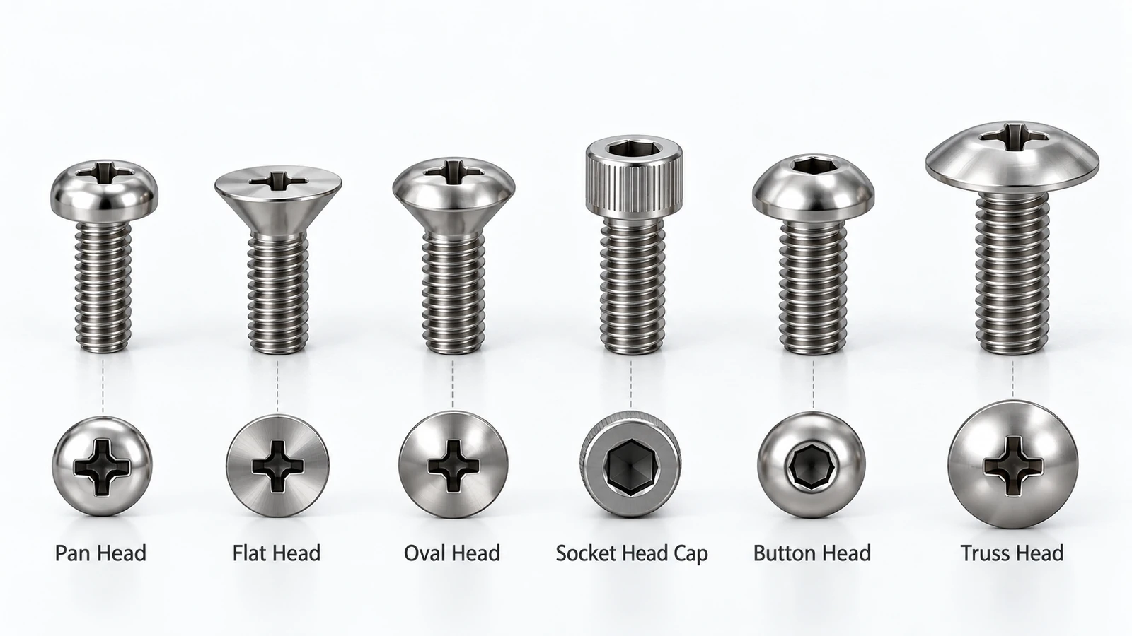
Head style and drive type are separate specifications.
For example, a pan-head screw may use a Phillips, slotted, or Torx drive, while socket-head cap screws commonly use internal hex drives.
For precision mechanical assemblies, select the head style based on available installation space, required bearing area, tool access, and the applicable fastening standard.
How to Choose the Right Machine Screw Size
Choosing the correct machine screw requires more than matching the outside diameter.
The following factors should be considered.
Match the Thread Specification
The screw must match the mating thread in nominal diameter, pitch, thread form, and compatible tolerance class.
For existing tapped holes, always identify the original thread specification before ordering replacement screws.
Do not substitute a similar metric size for a US size.
Select the Appropriate Screw Length
Screw length should provide sufficient engagement in the mating threads without bottoming out in a blind hole.
The required engagement depends on screw strength, internal-thread material, loading, and joint design.
A thread engagement length of approximately one nominal diameter is sometimes used as a preliminary guideline for steel-on-steel joints, but it is not a universal design rule.
Soft materials, thin walls, and highly loaded connections may require different engagement lengths or threaded inserts.
Consider Material and Corrosion Resistance
Carbon steel machine screws are widely used in general machinery, while stainless steel is useful where corrosion resistance is important.
Brass screws may be selected for electrical, decorative, or specific corrosion-related applications.
For high-load connections, material strength and property class are critical. The highest-strength screw is not automatically the best option if corrosion, temperature, or mating-material compatibility is more important.
Use Standard Sizes Whenever Possible
Standard machine screws are generally more economical and easier to source than custom-designed fasteners.
Custom CNC machining may be justified when the design requires:
- Nonstandard shaft diameters or shoulders
- Special undercuts or integrated spacers
- Precision concentric features
- Unusual materials or head geometries
- Multiple turned features that cannot be obtained from standard catalog screws
For small custom fasteners and complex threaded shaft components, CNC turning or Swiss-type machining may provide better dimensional control and reduce secondary operations.
Before specifying a custom machine screw, confirm whether a standard fastener can meet the same functional requirements at a lower total cost.
Conclusion
Machine screw sizing begins with identifying the correct nominal diameter, thread pitch, and length. US screws are commonly specified using numbered sizes and threads per inch, while metric screws use millimeter diameters and thread pitches.
Use the US and metric machine screw size charts to identify common specifications, and verify the mating thread before installation. Head style, material, engagement length, and mechanical loading should also be considered when selecting a fastener.
For standard assemblies, commercially available machine screws are usually the simplest solution. When a component requires nonstandard dimensions or precision-machined features, custom CNC turning or Swiss machining can provide additional design flexibility.
Frequently Asked Questions
A #8 machine screw has a nominal major diameter of 0.164 inches, approximately 4.17 mm. Common thread options include #8-32 UNC and #8-36 UNF.
An M4 screw has a nominal diameter of 4.0 mm, while a #8 screw measures approximately 4.17 mm. Their thread pitches also differ, so they should not be treated as interchangeable.
Many machine screws are fully threaded, particularly smaller sizes, but some designs include an unthreaded shank. Thread length depends on the product standard, overall length, and screw configuration.
Yes, when the plastic component includes a compatible threaded insert or a properly engineered internal thread. Repeated installation into directly tapped plastic may cause thread wear or stripping, depending on the material and design.
Custom machining is appropriate when standard screws cannot meet critical requirements such as unusual geometry, close concentricity, special materials, or integrated shaft features. For conventional fastening applications, standard screws are usually the more economical choice.



